Ball screw pair-driven clamping mechanism

A technology of ball screw pair and mold clamping mechanism, which is applied in the field of mold clamping mechanism driven by ball screw pair, can solve the problems of low control precision, difficult maintenance, easy wear, etc., and achieve high control precision, prolong service life, and positioning accurate effect

Inactive Publication Date: 2013-05-01
ZHEJIANG UNIV
View PDF2 Cites 10 Cited by
  • Summary
  • Abstract
  • Description
  • Claims
  • Application Information

AI Technical Summary

Problems solved by technology

[0003] The purpose of the present invention is to provide a mold clamping mechanism driven by a ball screw pair to solve the defects of the existing hydraulic drive mold clamping system, such as low control precision, easy wear, difficult maintenance, high noise, and high energy consumption.

Method used


Image

  • Ball screw pair-driven clamping mechanism
  • Ball screw pair-driven clamping mechanism
  • Ball screw pair-driven clamping mechanism

Examples


Embodiment Construction

[0013] The present invention will be further described below in conjunction with the accompanying drawings, and the purpose and effect of the present invention will become more obvious.

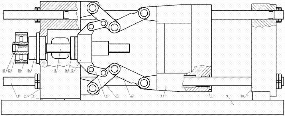
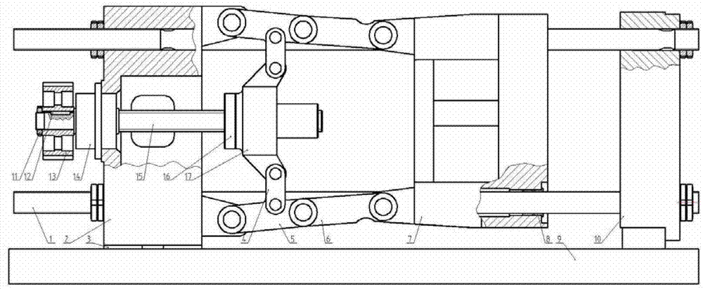
[0014] Such as figure 1 and figure 2 As shown, the clamping mechanism of the ball screw pair transmission of the present invention includes: four pull rods 1, tail plate 2, two toggle mechanisms, movable template 7, head plate 10, synchronous pulley 13, screw bearing housing 14, Ball screw 15, ball nut 16, thrust seat 17.

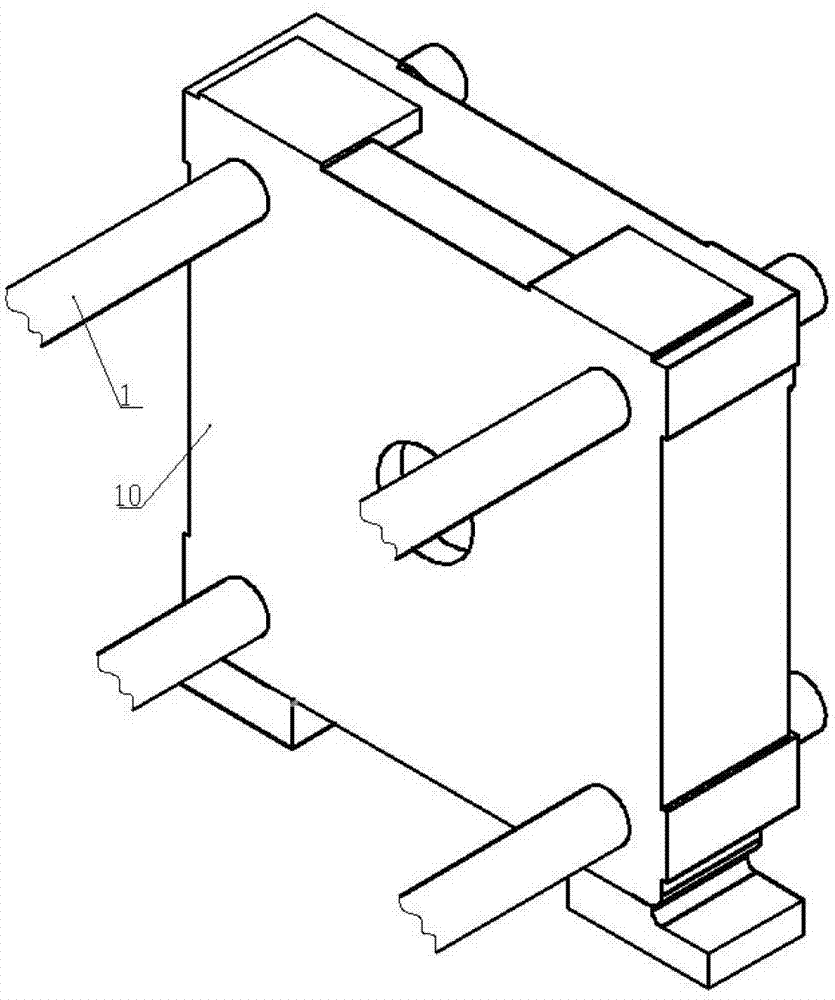
[0015] Corresponding four tie rod holes are provided on the head plate 10, the movable template 7 and the tail plate 2. Such as image 3 shown. One end of four pull rods 1 is all fixed on the head plate 10, and the other end is fixed on the tail plate 2 after passing through the pull rod holes of the movable formwork 7. Four pull rods 1 fix the distance between the head plate 10 and the tail plate 2, and are used for the motion guidance of the movable template 7. Th...


PUM


Abstract

The invention discloses a ball screw pair-driven clamping mechanism. The ball screw pair-driven clamping mechanism comprises four pull rods, a tail plate, two toggle mechanisms, a movable mould plate, a head plate, a synchronous pulley, a screw bearing base, a ball screw, a ball nut and a thrust block, wherein the four pull rods fix the distance between the head plate and the tail plate and are used for guiding movement of the movable mould plate. The ball screw pair-driven clamping mechanism is driven by a servo motor; and through a toothed synchronous belt and a ball screw pair, rotation of the motor is converted into back-and-front movement of the thrust block to drive a toggle link mechanism so as to open and close the movable mould plate.

Description

technical field [0001] The invention relates to a mold clamping mechanism of an injection molding machine, in particular to a mold clamping mechanism driven by a ball screw pair. Background technique [0002] In the mold clamping parts of the traditional injection molding machine, the thrust seat is pushed forward and backward by the hydraulic cylinder, and the force is amplified by the toggle mechanism to obtain the opening and closing action of the movable platen and a large enough clamping force. However, the traditional hydraulic drive system has many defects. First, its characteristics are difficult to maintain after continuous operation and oil temperature changes, and the control accuracy is affected; second, the hydraulic system is prone to wear and noise due to large inertia; third, the operation Difficult maintenance and high energy consumption during the period. Therefore, it is driven by a servo motor and driven by a ball screw, and a new mold clamping mechanism...

Claims


Application Information

Patent Timeline
Patent Type & Authority Applications(China)
IPC IPC(8): B29C45/66
Inventor 李凌丰张振然管灵波茅旭飞
Owner ZHEJIANG UNIV
Why Eureka
Try Eureka