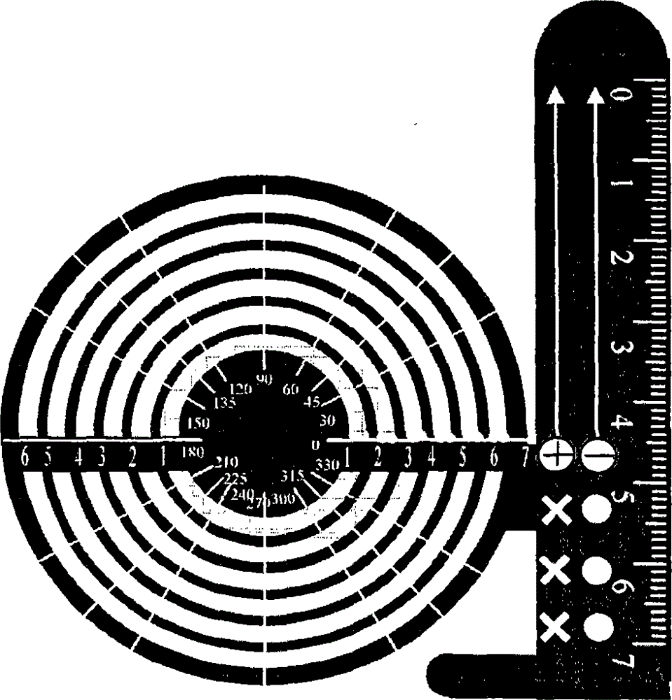
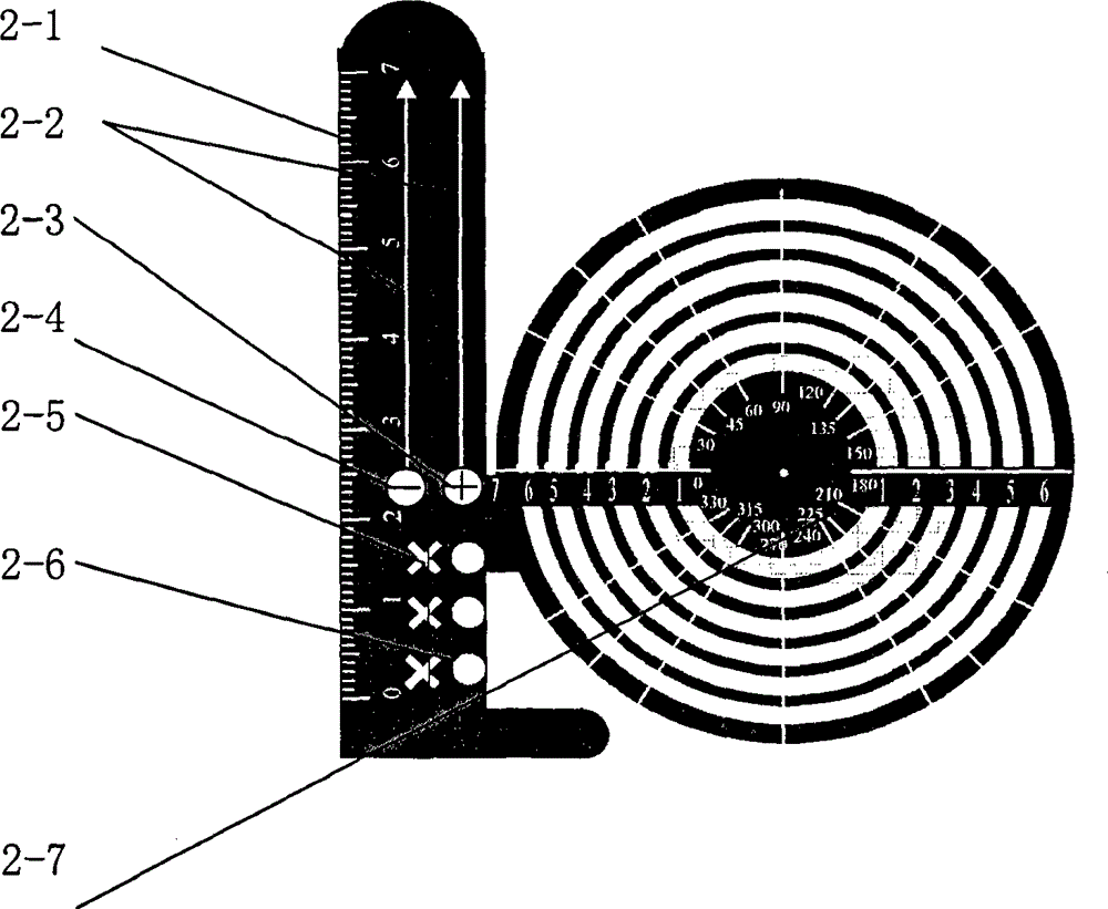
Drawing device with functions of set square, compasses and protractor
A drawing tool and technology of concentric circles, applied in the field of drawing tools, can solve problems such as unsatisfactory problem-solving effects and high difficulty for students, and achieve the effects of simple and reasonable structure, improved efficiency, and convenient use
- Summary
- Abstract
- Description
- Claims
- Application Information
AI Technical Summary
Problems solved by technology
Method used
Image

Examples
Embodiment 1
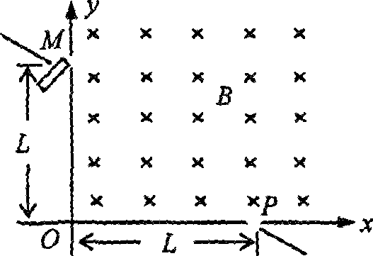
[0039] (2009 Fujian Volume 22) image 3 It is a simplified schematic diagram of a device that can measure the specific charge. In the first quadrant area, there is a uniform magnetic field perpendicular to the surface of the paper, and the magnetic induction intensity is B=2.0×10 -3 T, on the x-axis, the place P at L=0.50m away from the coordinate origin is the entrance of the ion, and the receiver is placed on the y. Now the positively charged particle is v=3.5×10 4 The rate of m / s is injected into the magnetic field from P. If the particle is observed at M on the y-axis at a distance of L=0.50m from the origin of coordinates, and the radius of the trajectory is just the smallest, let the mass of the charged particle be m and the electric quantity be q , regardless of its gravity. (1) Calculate the specific charge of the above particles (2) If a uniform electric field is added in the first quadrant at a certain moment during the movement of the above particle, it can make...
Embodiment 2
[0049] (2011 Guangdong 35 questions) such as Figure 5 As shown in (a), with O as the center, the inner and outer radii are R 1 and R 2 In the ring area of , there is a radial electric field and a uniform magnetic field perpendicular to the paper surface, the potential difference U between the inner and outer circles is constant, and R 1 =R 0 ,R2 = 3R 0 , a particle with a charge of +q and a mass of m enters the area from point A on the inner circle, regardless of gravity.
[0050] (1) It is known that the particle travels from the outer circle with a velocity v 1 Eject, find the initial velocity v of the particle at point A 0 the size of
[0051] (2) If the electric field is removed, such as Figure 5 (b), it is known that the particle travels from the intersection C of the extension line of OA and the outer circle with a velocity v 2 Injection, the direction is at an angle of 45° to the 0A extension line, find the magnitude of the magnetic induction and the time fo...
Embodiment 3
[0072] (2009 Zhejiang 25 questions) such as Figure 8 As shown, the positive direction of the x-axis is horizontal to the right, and the positive direction of the y-axis is vertically upward. There is a uniform electric field parallel to the y-axis in the xOy plane, and a uniform magnetic field perpendicular to the xOy plane in a circle with a radius R. A charged particle emitting device is placed on the left side of the circle, which emits a beam of charged particles with the same mass m, charge q (q>0) and initial velocity v along the positive direction of the x-axis. When launching, this beam of charged particles is distributed in the interval of 0
PUM
 Abstract
Description
Claims
Application Information