Low-rotating-speed double-layer propcopter

A propeller, low-speed technology, applied in the field of aviation helicopters, can solve the problems of large engine wear, short service life and high manufacturing cost, and achieve the effects of low cost, long service life and improved power utilization rate

Active Publication Date: 2013-05-01
黄春水
View PDF6 Cites 8 Cited by
  • Summary
  • Abstract
  • Description
  • Claims
  • Application Information

AI Technical Summary

Problems solved by technology

[0002] At present, there are various helicopters in the world, but these helicopters can only obtain sufficient lift under the premise of high speed of the propeller, and the wear and tear of the engine is large, the service life is short, and the failure rate is high under the condition of high speed. High and less secure
In addition, the high-speed rotation of the propeller requires a large horsepower, so a large engine is required, resulting in a heavy fuselage, high fuel consumption, and high manufacturing costs.

Method used


Image

  • Low-rotating-speed double-layer propcopter
  • Low-rotating-speed double-layer propcopter
  • Low-rotating-speed double-layer propcopter

Examples


Embodiment 1

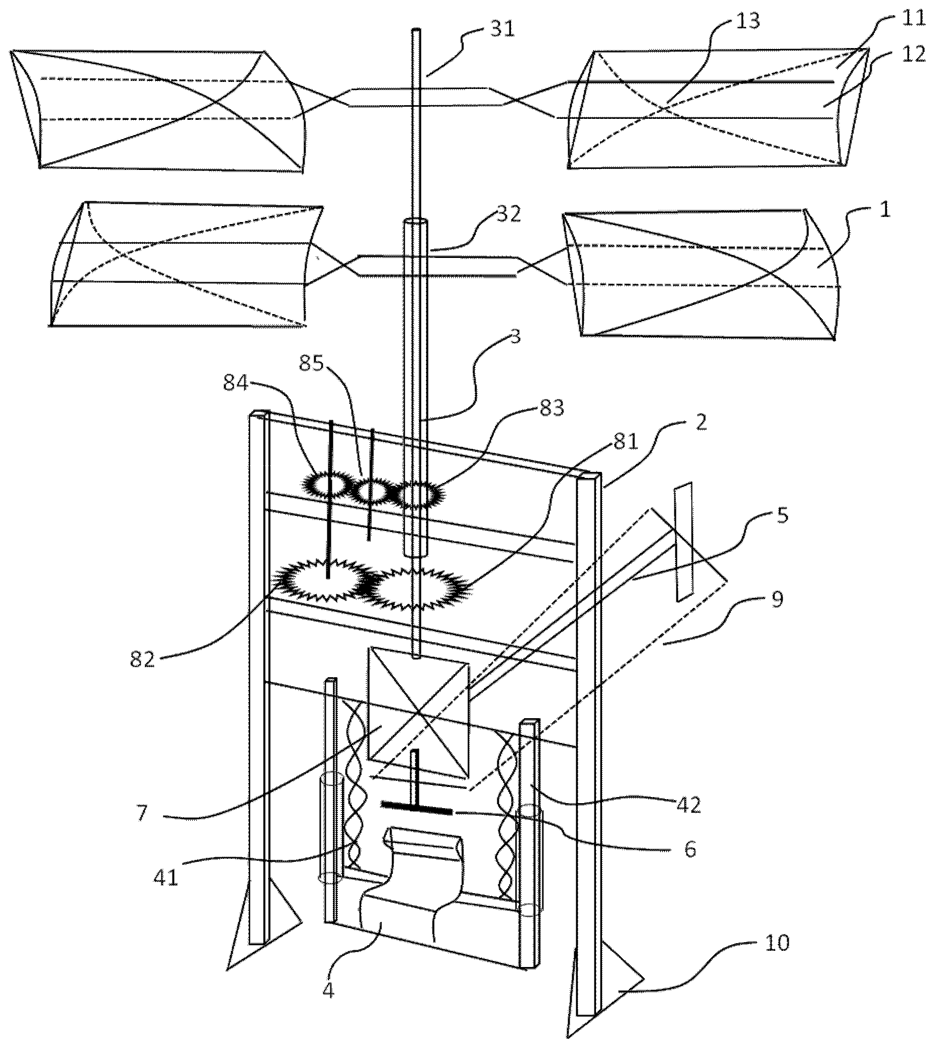
[0022] Low speed double deck propeller helicopters, such as figure 1 As shown, it includes a frame 2 and a propeller 1 , the propeller 1 is installed on a central shaft 3 , and the central shaft 3 is mounted on the frame 2 .

[0023] The central shaft 3 includes a first rotating shaft 31 and a second rotating shaft 32 , and the second rotating shaft 32 is sleeved on the outside of the first rotating shaft 31 . The upper propeller is installed on the upper end of the first rotating shaft 31 , and the lower propeller is installed on the upper end of the second rotating shaft 32 .

[0024] combine figure 1 , image 3 , Figure 4 and Figure 5 , the propeller 1 is provided with two layers, namely an upper layer propeller and a lower layer propeller. The propeller includes two blades 11 , and the two blades 11 are respectively arranged on both sides of the central shaft 3 through a connecting rod 12 . The lower surface of the blade 11 is provided with a concave structure 13. ...

Embodiment 2

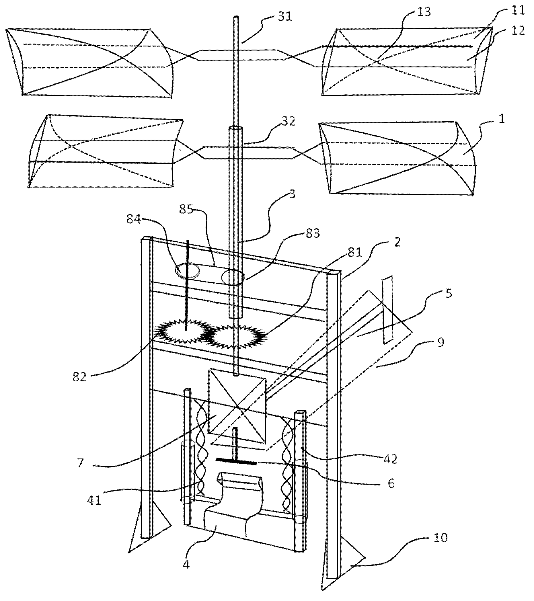
[0031] Low speed double deck propeller helicopters, such as figure 2 As shown, the basic structure is the same as that of Embodiment 1, except that the rotation direction of the upper propeller is controlled opposite to that of the lower propeller. The implementation of this embodiment is: the third gear and the fourth gear in Embodiment 1 are replaced by the first pulley 83 and the second pulley 84, the fifth gear is removed, and the first pulley 83 and the second pulley 84 The transmission belt 85 is put on the top, and the first gear 81 is driven by the engine 7. The rotation of the first gear 81 drives the second gear 82, and the rotation of the second gear 82 drives the second gear coaxial with it. Belt pulley 84 rotates, and because of the transmission effect of described transmission belt 85, then drives first belt pulley 83 to rotate and finally drives second rotating shaft 32 to rotate, has realized that the direction of rotation of the upper propeller and the direct...


PUM


Abstract

The invention discloses a low-rotating-speed double-layer propcopter which comprises a rack and propellers, wherein the propellers are mounted on the rack by a center shaft; the double-layer propellers are the upper-layer propeller and the lower-layer propeller respectively; a rotating direction of the upper-layer propeller is opposite to that of the lower-layer propeller; each of the upper-layer propeller and the lower-layer propeller comprises two blades respectively; every two blades are symmetrically arranged on the two sides of the center shaft respectively by a connecting rod; concave structures are formed on the lower surfaces of the blades; when the load capacity is 200kg, the corresponding area sum of the four blades is 6-15m<2>; the length of each blade is 1.8-2.5m; and the width of each blade is 0.6-1.5m. The low-rotating-speed double-layer propcopter has the advantages that the large-blade propellers have lower rotating speeds, the abrasion of accessories is less, the service life is longer, a failure rate is lower, a use ratio of engine power is increased, engines with smaller sizes can be adopted, the mass is lighter, the cost is lower, more energy is saved, and a market prospect is better.

Description

【Technical field】 [0001] The invention relates to the technical field of aviation helicopters, in particular to a low-speed double-layer propeller helicopter. 【Background technique】 [0002] At present, there are various helicopters in the world, but these helicopters can only obtain sufficient lift under the premise of high speed of the propeller, and the wear and tear of the engine is large, the service life is short, and the failure rate is high under the condition of high speed. High and less secure. In addition, the high-speed rotation of the propeller requires a large horsepower, so a large engine is required, resulting in a heavy fuselage, high fuel consumption, and high manufacturing costs. 【Content of invention】 [0003] The purpose of the present invention is to address the shortcomings of the above-mentioned prior art, and to invent a low-speed double-layer propeller helicopter with double-layer propellers, large propeller blades, simple structure and more ener...

Claims


Application Information

Patent Timeline
Patent Type & Authority Applications(China)
IPC IPC(8): B64C27/10B64C27/14B64C27/46
Inventor 黄春水
Owner 黄春水
Why Eureka
Try Eureka