Centrifugal flywheel

A centrifugal and flywheel technology, applied in the field of flywheels, can solve problems such as difficult to further improve the stability of mechanical operation, and achieve the effect of improving the stability of operation and increasing the moment of inertia

Inactive Publication Date: 2013-05-01
ZHEJIANG UNIV
View PDF9 Cites 5 Cited by
  • Summary
  • Abstract
  • Description
  • Claims
  • Application Information

AI Technical Summary

Problems solved by technology

It can be seen that after the flywheel operates at the rated speed, it i

Method used


Image

  • Centrifugal flywheel
  • Centrifugal flywheel
  • Centrifugal flywheel

Examples


Embodiment Construction

[0025] The present invention will be further described below in conjunction with accompanying drawings and examples of implementation.

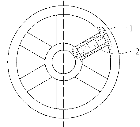
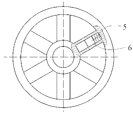
[0026] Such as figure 1 , figure 2 , image 3 As shown, the present invention is provided with a centrifugally moving cylinder in each spoke slideway of the flywheel, or a cylinder with a spring storing and releasing elastic deformation energy in each spoke slideway of the flywheel.

[0027] Such as figure 1 As shown, the two ends of the cylinder 2 in the six spoke slideways are full of viscous medium 1. The cylinder 2 is located in the slideway and can slide radially along the flywheel, and the slideway is filled with a viscous medium 1 to lubricate the movement of the cylinder.

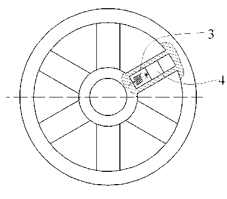
[0028] Such as figure 2 As shown, one end surface of the cylinder 4 near the center in the six spoke slideways is a tension spring 3 . The cylinder 4 is located in the slideway, and is connected with the hub part of the flywheel through the tension spring 3...


PUM


Abstract

The invention discloses a centrifugal flywheel. A cylinder which moves centrifugally is arranged in each spoke slipway of the flywheel; and an adhesive medium is filled into the cylinder; or a cylinder for storing and releasing elastic deformation energy of a spring is arranged in each spoke slipway of the flywheel. The cylinder provided by the invention can slide in the slipway, and slides towards the edge of the flywheel after the flywheel starts running, so that the rotation inertia of the flywheel is increased, and the running stability of a machine is improved; the adhesive medium is filled into the slipway, and plays a role in lubricating in the sliding process of the cylinder; and the cylinder is connected with the flywheel by stretching or compressing the spring to form an energy storing element, so that the rotation inertia can be changed and the elastic deformation energy can be stored and released after the flywheel starts running, and the running stability of the machine is further improved.

Description

technical field [0001] The invention relates to a flywheel, in particular to a centrifugal flywheel with variable moment of inertia. Background technique [0002] The flywheel is a moment of inertia A large rotating body, its function is to adjust the periodic speed fluctuation of the machine. flywheel angular velocity The kinetic energy during rotation is [0003] (1) [0004] Maximum angular velocity with flywheel , minimum angular velocity Correspondingly, its kinetic energy is the maximum kinetic energy , minimum kinetic energy . and The difference represents the maximum change in kinetic energy in one cycle [0005] (2) [0006] is the average angular velocity of the flywheel, , which is equivalent to the axle speed; is the non-uniformity coefficient of the mechanical running speed, , The smaller the value, the more stable the mechanical operation. [0007] According to formula (2), we can s...

Claims


Application Information

Patent Timeline
IPC IPC(8): F16F15/31
Inventor 程超汪久根
Owner ZHEJIANG UNIV
Why Eureka
Try Eureka