Fresh air conditioning unit capable of realizing energy recovery and free cooling

A technology for energy recovery and fresh air conditioning, which is used in energy recovery systems for ventilation and heating, air conditioning systems, space heating and ventilation, etc.

Active Publication Date: 2014-12-03
任承钦
View PDF5 Cites 3 Cited by
  • Summary
  • Abstract
  • Description
  • Claims
  • Application Information

AI Technical Summary

Problems solved by technology

[0009] As far as the existing fresh air air conditioner units are concerned, such as paper-based all-purpose heat exchange fresh air air conditioner units, etc., they cannot integrate the above energy-saving methods well, so as to give full play to the functions of energy recovery and free cooling.

Method used


Image

  • Fresh air conditioning unit capable of realizing energy recovery and free cooling
  • Fresh air conditioning unit capable of realizing energy recovery and free cooling
  • Fresh air conditioning unit capable of realizing energy recovery and free cooling

Examples


Embodiment 1

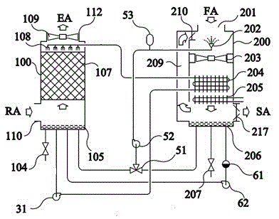
[0052] refer to figure 1 , this embodiment includes a fresh air system and an exhaust system. The fresh air system includes a casing I200, a fan I203, a first energy recovery fresh air heat exchanger 204, and a fresh air system pool 206. The casing I200 is provided with a fresh air inlet 201 and a fresh air The air outlet 217, the lower end of the shell I200 is connected to the fresh air system pool 206, the fan I203 and the first energy recovery fresh air heat exchanger 204 are installed in the shell I200 along the fresh air flow route, and the fresh air system pool 206 is equipped with Water supply valve 207, the exhaust system includes casing II 100, fan II 109, liquid distributor 108, packed bed heat and mass exchanger 107, exhaust system pool 105, and the casing II 100 is provided with an exhaust inlet 110 and an exhaust outlet 112, the lower end of the shell II 100 is connected to the pool 105 of the exhaust system, the packed bed heat and mass exchanger 107 is installed...

Embodiment 2

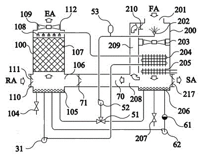
[0074] refer to figure 2 , The difference between this embodiment and Embodiment 1 is that a fresh air-exhaust air bypass passage 70 is provided between the fresh air system and the exhaust air system, and a fresh air-exhaust air bypass passage 70 is provided in the fresh air-exhaust air bypass passage 70. Bypass air valve 71, the inlet 208 of the fresh air-exhaust air bypass passage 70 is located on the air passage after the first energy recovery fresh air heat exchanger 204 of the fresh air system, and the outlet 106 of the fresh air-exhaust air bypass passage 70 is located On the air duct before the packed bed heat and mass exchanger 107 of the air system.

[0075] Under dry and hot climate conditions, by opening the fresh air-exhaust air bypass valve 71, a part of the cooled fresh air can be directly entered into the exhaust system from the fresh air system, and mixed with the exhaust air from the indoor air (RA), so that the packing The evaporative cooling effect in the...

Embodiment 3

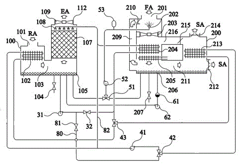
[0078] refer to image 3 The difference between this embodiment and Embodiment 1 is that: the fresh air system is provided with a second energy recovery fresh air heat exchanger 213, and there are two fresh air supply ports, that is, the first fresh air supply port 214 and the second fresh air supply port 212, the casing is provided with a fresh air system internal bypass air passage 216, a fresh air system internal bypass air valve 215, and a fresh air system internal connecting air duct 211, and the outlet of the fresh air system internal connecting air duct 211 is directly connected to the second fresh air supply port 212 , the outlet of the bypass duct 216 inside the fresh air system is directly connected to the first fresh air supply port 214; the exhaust system is provided with a surface heat exchanger 102, and the surface heat exchanger 102 is located in the heat mass of the packed bed Before the exchanger 107, an internal air duct 103 of the exhaust system is provided ...


PUM


Abstract

A fresh air conditioning unit capable of realizing energy recovery and free cooling comprises a fresh air system and an air exhausting system, wherein a circulating pump is arranged between the fresh air system and the air exhausting system, an inlet of the circulating pump is connected with an exhausting system water pond through a pipeline, an outlet of the circulating pump is connected with an inlet of a first energy recovery fresh air heat exchanger through a pipeline, an outlet of the first energy recovery fresh air heat exchanger is connected with a liquid distributor through a pipeline to form a water or aquatic solution circulating system for realizing full heat energy recovery and free cooling circulation; and a water or aquatic solution atomizing system for humidifying the fresh air is arranged inside the fresh air system. Due to the adoption of the fresh air conditioning unit, the high-efficient energy conservation can be realized by adequately playing the effects of the energy recovery, free cooling and energy consumption reduction in a reheating process through appropriate running adjusting mechanism under different weather conditions.

Description

technical field [0001] The invention relates to a fresh air air conditioning unit, in particular to a fresh air air conditioning unit capable of realizing energy recovery and free cooling. Background technique [0002] According to the current level of air conditioning technology, if an ideal fresh air air conditioning process is to be achieved under all working conditions to meet the needs of indoor temperature and humidity control, a fresh air air conditioning unit usually not only needs to be associated with a heat pump, but also requires electric heating. With the aid of an electric heater or even an electric steam humidifier, the fresh air air conditioning process consumes a lot of energy and has low energy efficiency. [0003] In the cooling season, because the dehumidification process is also achieved through the cooling process, the heat pump needs to bear the entire cooling load of the fresh air cooling and dehumidification process in the fresh air air conditioning ...

Claims


Application Information

Patent Timeline
Patent Type & Authority Patents(China)
IPC IPC(8): F24F3/14F24F12/00
Inventor 任承钦
Owner 任承钦
Why Eureka
Try Eureka