Fresh air conditioning unit capable of realizing energy recovery and free cooling
A technology of energy recovery and fresh air air conditioning, applied in energy recovery systems for ventilation and heating, air conditioning systems, space heating and ventilation, etc.
- Summary
- Abstract
- Description
- Claims
- Application Information
AI Technical Summary
Problems solved by technology
Method used
Image
Examples
Embodiment 1
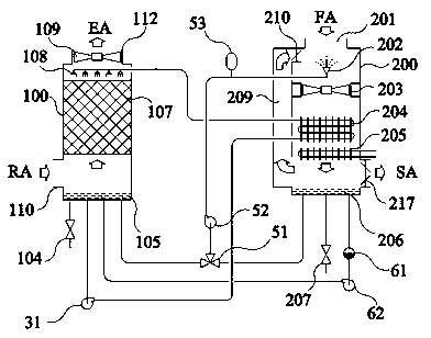
[0052] refer to figure 1 , This embodiment includes a fresh air system and an exhaust system. The fresh air system includes a casing I200, a fan I203, a first energy recovery fresh air heat exchanger 204, and a fresh air system pool 206. The casing I200 is provided with a fresh air inlet 201 and a fresh air Air supply port 217, the lower end of the casing I200 is connected to the fresh air system pool 206, the fan I203 and the first energy recovery fresh air heat exchanger 204 are installed in the casing I200 along the fresh air flow path, and the fresh air system pool 206 is provided with The water replenishment valve 207, the exhaust system includes a casing II 100, a fan II 109, a liquid distributor 108, a packed bed heat and mass exchanger 107, and an exhaust system pool 105. The casing II 100 is provided with an exhaust inlet 110 and an exhaust outlet. 112. The lower end of the shell II 100 is connected to the pool 105 of the exhaust system, the packed bed heat and mass e...
Embodiment 2
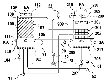
[0074] refer to figure 2 The difference between this embodiment and Embodiment 1 is that a fresh air-exhaust bypass duct 70 is arranged between the fresh air system and the exhaust system, and a fresh air-exhaust air passage 70 is arranged in the fresh air-exhaust bypass duct 70 Bypass valve 71, the inlet 208 of the fresh air-exhaust bypass duct 70 is located on the air duct behind the first energy recovery fresh air heat exchanger 204 of the fresh air system, and the outlet 106 of the fresh air-exhaust bypass duct 70 is located in the exhaust duct 70. On the air duct before the packed bed heat and mass exchanger 107 of the air system.
[0075] In hot and dry climates, by opening the fresh air-exhaust bypass ventilation valve 71, a part of the cooled fresh air can be directly entered into the exhaust system from the fresh air system, and mixed with the exhaust air from the indoor air (RA), so that the filler Evaporative cooling in the bed heat and mass exchanger 107 is bette...
Embodiment 3
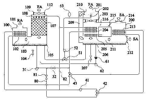
[0078] refer to image 3 The difference between this embodiment and Embodiment 1 is that the fresh air system is provided with a second energy recovery fresh air heat exchanger 213, and the fresh air supply ports are two, namely the first fresh air supply port 214 and the second fresh air supply port 212, the shell is provided with an internal bypass duct 216 of the fresh air system, an internal bypass vent valve 215 of the fresh air system, and an internal connection air duct 211 of the fresh air system, and the outlet of the internal connection air duct 211 of the fresh air system is directly connected to the second fresh air supply port 212. , the outlet of the bypass duct 216 inside the fresh air system is directly connected to the first fresh air supply port 214; the surface heat exchanger 102 is arranged in the exhaust system, and the surface heat exchanger 102 is located in the thermal mass of the packed bed Before the exchanger 107, there is an internal air duct 103 of...
PUM
 Abstract
Description
Claims
Application Information
 - R&D
- Intellectual Property
- Life Sciences
- Materials
- Tech Scout
- Unparalleled Data Quality
- Higher Quality Content
- 60% Fewer Hallucinations
Browse by: Latest US Patents, China's latest patents, Technical Efficacy Thesaurus, Application Domain, Technology Topic, Popular Technical Reports.
© 2025 PatSnap. All rights reserved.Legal|Privacy policy|Modern Slavery Act Transparency Statement|Sitemap|About US| Contact US: help@patsnap.com


