Cold gas carrying spray head structure of direct contact type ice slurry generator

A gas nozzle, contact technology, applied in the field of direct contact ice slurry generator cooling gas nozzle structure, to achieve the effect of saving investment cost, reducing leakage and reducing maintenance cost

Inactive Publication Date: 2015-01-28
ZHEJIANG UNIV
View PDF8 Cites 0 Cited by
  • Summary
  • Abstract
  • Description
  • Claims
  • Application Information

AI Technical Summary

Problems solved by technology

[0004] The purpose of the present invention is to solve the problems faced by the practical application of the gas direct contact ice slurry production system, and provide a direct contact ice slurry generator cooling gas nozzle structure

Method used


Image

  • Cold gas carrying spray head structure of direct contact type ice slurry generator
  • Cold gas carrying spray head structure of direct contact type ice slurry generator
  • Cold gas carrying spray head structure of direct contact type ice slurry generator

Examples


Embodiment Construction

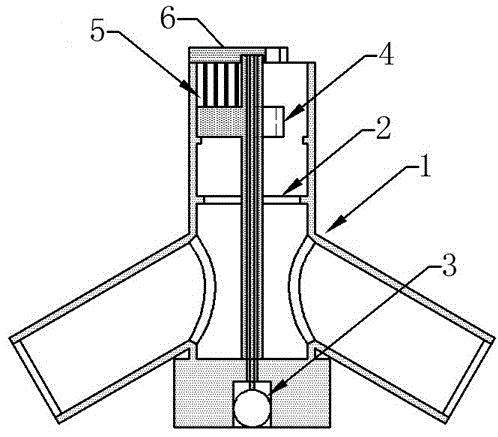
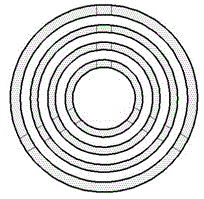
[0019] As shown in the figure, the structure of the cold-carrying gas nozzle of the direct contact ice slurry generator includes a gas tee structure 1, a wire mesh 2, a gear motor 3, a waterproof casing and support ribs 4, a concentric annular flow channel 5 and a deicer 6 , the deicer 6 includes a transmission shaft 6.1, a bracket 6.2, a deicing blade 6.3, and a waterproof groove 6.4; a mesh 2 is provided in the middle of the gas tee structure 1, a reduction motor 3 is provided at the lower end, and a concentric annular flow channel 5 is provided at the upper end , the deceleration motor 3 is connected to the lower end of the transmission shaft 6.1, the transmission shaft 6.1 is provided with a waterproof sleeve and a support rib 4, the concentric annular flow channel 5 is fixed on the waterproof sleeve and the support rib 4, and the lower surface of the bracket 6.2 is vertically provided with a deicing The blade 6.3 and the bracket 6.2 are 3 arms at 120 degrees. The lower end...


PUM


Abstract

The invention discloses a cold gas carrying spray head structure of a direct contact type ice slurry generator. The cold gas carrying spray head structure comprises a gas three-way structure, a silk screen, a speed reduction motor, a waterproof sleeve pipe, a supporting rib, a concentric annular flow channel and a deicer, wherein the deicer comprises a transmission shaft, a bracket, a deicing blade and a waterproof groove; the silk screen is arranged in the middle of the gas three-way structure; the speed reduction motor is arranged at the lower end of the gas three-way structure; the concentric annular flow channel is formed in the upper end of the gas three-way structure; the speed reduction motor is connected with the lower end of the transmission shaft; the waterproof sleeve pipe and the supporting rib are arranged outside the transmission shaft; the concentric annular flow channel is fixed to the supporting rib; the deicing blade is vertically arranged on the lower surface of the bracket; the bracket comprises three arms at an angle of 120 degrees; the lower end of the deicing blade extends into the concentric annular flow channel; and the waterproof groove is formed in the joint of the bracket and the upper end of the transmission shaft. According to the cold gas carrying spray head structure, the ice blockage phenomenon in the operation of the ice slurry generator can be effectively prevented, the leakage amount of an ice-making solution of a system is reduced, and the stable and efficient operation of the ice slurry making system is facilitated.

Description

technical field [0001] The invention relates to the field of energy air conditioning, in particular to a structure of a direct contact ice slurry generator cooling gas spray head. Background technique [0002] Gas direct contact method ice slurry production system [Patent No. ZL 2009 1 0102116.5] uses air, nitrogen and other environmentally friendly working fluids as refrigerants to directly contact and exchange heat with ice-making solution to produce ice slurry. The use of gas as the refrigerant can reduce system investment and maintenance costs, and at the same time avoid the problem of cold storage liquid pollution caused by the liquid refrigerant dissolving into the ice-making solution. [0003] However, the aforementioned ice slurry production system has the following problems: 1. After the ice-making solution at the nozzle of the ice-slurry generator is overcooled, the ice crystals accumulate seriously, and ice blockage is very likely to occur, which affects the stabl...

Claims


Application Information

Patent Timeline
Patent Type & Authority Patents(China)
IPC IPC(8): F25C1/00
Inventor 张学军王炜江敏邱利民甘智华张小斌孙大明
Owner ZHEJIANG UNIV
Why Eureka
Try Eureka