Two-phase cross-connected micro-channel heat sink

Inactive Publication Date: 2009-06-04
UNIV OF HAWAII
View PDF63 Cites 7 Cited by
  • Summary
  • Abstract
  • Description
  • Claims
  • Application Information

AI Technical Summary

Benefits of technology

[0005]In accordance with the present invention, an improved two-phase micro-channel heat sink comprises: a plurality of flow micro-channels extending in parallel in a longitudinal direction and having channel walls substantially symmetrical with each other of a given wall thickness and defining a flow channel width and height for accommodating a flow of liquid coolant therein; and a plurality of cro

Problems solved by technology

However, one practical concern that hinders the implementation of this powerful c

Method used


Image

  • Two-phase cross-connected micro-channel heat sink
  • Two-phase cross-connected micro-channel heat sink
  • Two-phase cross-connected micro-channel heat sink

Examples


Embodiment Construction

[0015]In the following detailed description of the invention, certain preferred embodiments are illustrated providing certain specific details of their implementation. However, it will be recognized by one skilled in the art that many other variations and modifications may be made given the disclosed principles of the invention.

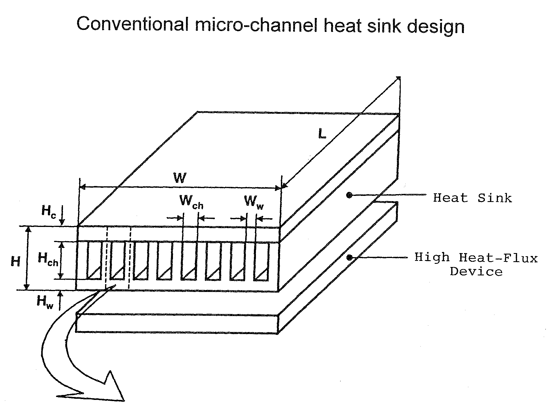
[0016]Micro-channel heat sinks have emerged as a prime contender for thermal management of next generation high-power-density electronic devices, whose key technical merits include low thermal resistance, small coolant inventory requirement, small coolant flow rate requirement, and small heat sink mass and volume. A heat sink is classified as a micro-channel heat sink by the characteristic dimensions of the flow passages. FIG. 3 illustrates the typical construction of a conventional micro-channel heat sink design. The micro-channel heat sink has a length L and width W and is comprised of parallel channel walls on a planar base substrate defining flow channels...


PUM


Abstract

An improved two-phase micro-channel heat sink has a plurality of flow micro-channels extending in parallel in a longitudinal direction for accommodating a flow of liquid coolant therein, and a plurality of cross-connected micro-channels extending in parallel in a transverse direction formed at regular intervals along the longitudinal direction for cross-connecting with the flow micro-channels. The cross-connected micro-channels enable a uniform pressure field to be maintained for two-phase flow boiling of liquid coolant in the heat sink. In a preferred embodiment, the heat sink contains flow micro-channels with width of 100 μm, wall thickness of 100 μm, and height of 600 μm, and cross-connected micro-channels of similar width and height cut at 1 mm intervals along the flow direction.

Description

[0001]This U.S. patent application claims the priority of Provisional Patent Application 61 / 004821 filed on Nov. 30, 2007, by the same inventor.TECHNICAL FIELD[0002]The present invention is directed to a heat sink device for efficient cooling of high-power-density electronic devices and, more particularly, to an improved design for a two-phase micro-channel heat sink.BACKGROUND OF INVENTION[0003]The ceaseless pursuit of improvement in performance of electronic devices with simultaneous reductions in weight and volume has sought improvements in efficient heat sink designs for ever-increasing dissipative waste heat densities. Current and near future high-performance commercial / defense electronic devices require heat fluxes on the order of 100 W / cm2 to be dissipated. As the reliability and life -span of electronics are both strongly affected by temperature, it is necessary to develop highly efficient cooling techniques to reduce the maintenance costs and increase the service life of hi...

Claims


Application Information

Patent Timeline
IPC IPC(8): F28F3/12
CPCH01L2924/0002F28F3/048H01L23/427H01L2924/00
Inventor QU, WEILIN
Owner UNIV OF HAWAII
Why Eureka
Try Eureka