Layered sampling testing device for capillary water zone

A sampling test and capillary water technology, applied in the direction of sampling devices, etc., can solve problems such as the inability to accurately study the change law of tailings dams, the inability to accurately analyze the stability of tailings dams, and the reduction of safety reserves of tailings dams, so as to achieve true measurement data Reliable, low-cost, easy-to-produce effects

Active Publication Date: 2013-05-01
NANHUA UNIV
View PDF5 Cites 15 Cited by
  • Summary
  • Abstract
  • Description
  • Claims
  • Application Information

AI Technical Summary

Problems solved by technology

In 2009, María et al. used numerical simulation methods to study the influence of capillary water on the stability of tailings dams, and proposed that the stability of tailings dams largely depends on the role of capillary water. The existence of capillary water makes tailings dams The safety reserve of the
[0005] Analyzing the research of María et al., it is found that the shortcoming is that the capillary water zone is used as a whole to analyze the stability of the tailings dam, and there will be a large deviation between the analysis results and the actual value
[0006] In the traditional capillary water test device, when the diameter of the device is small

Method used


Image

  • Layered sampling testing device for capillary water zone
  • Layered sampling testing device for capillary water zone
  • Layered sampling testing device for capillary water zone

Examples


Example Embodiment

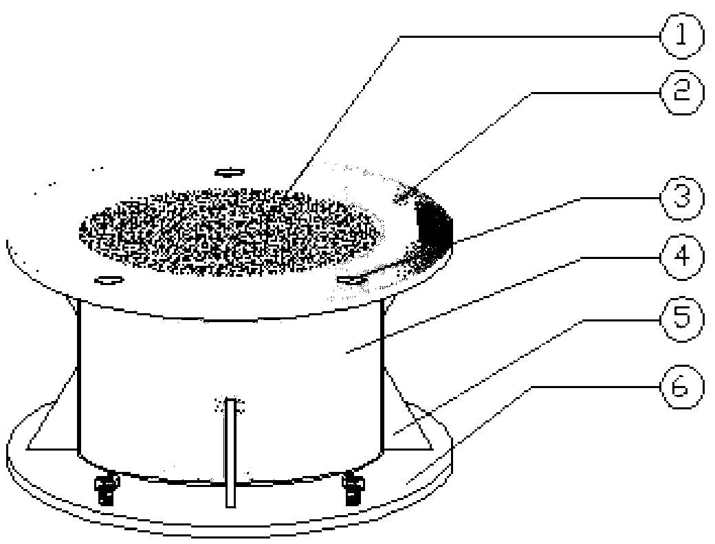
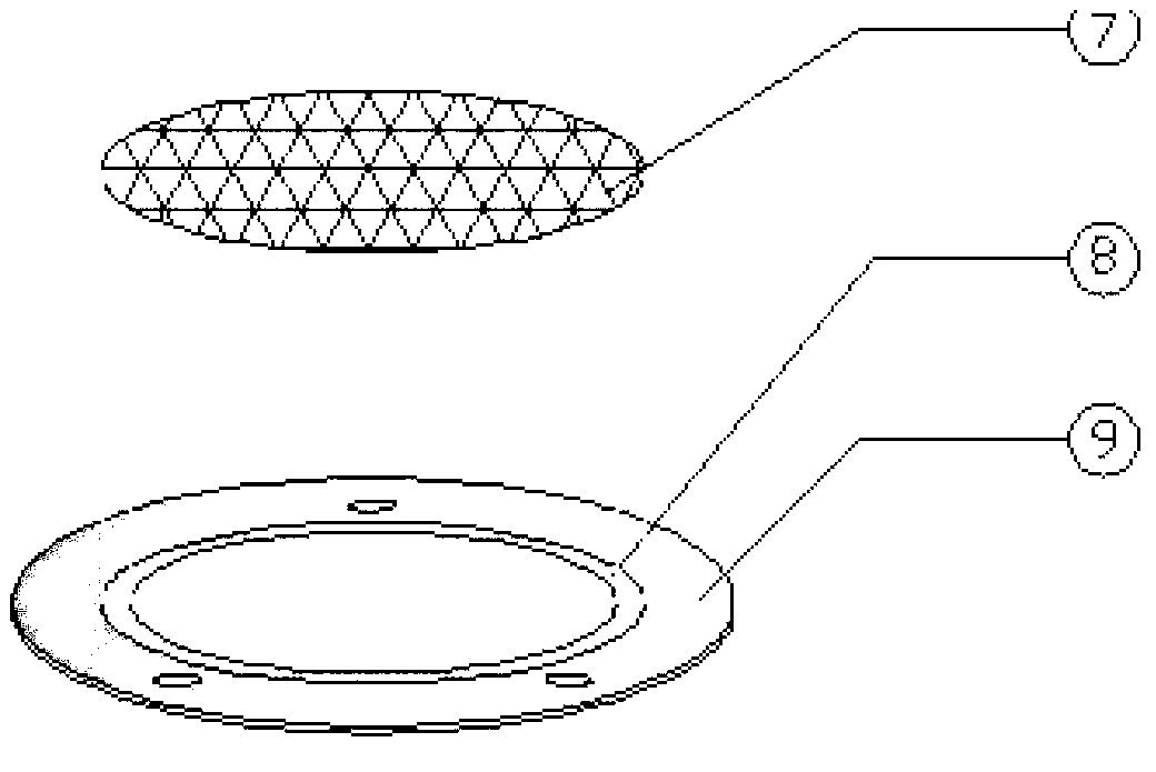
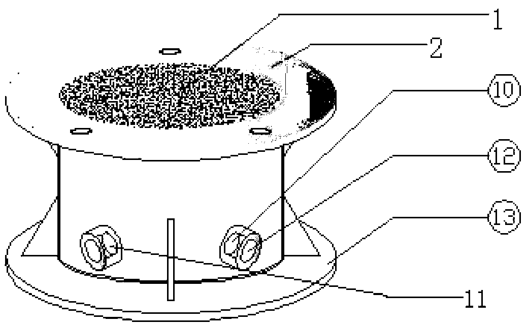
[0027] 1. Material composition

[0028] Unit column, base, tailings sand, water injection bottle.

[0029] 2. Material configuration and usage method

[0030] See the attachment for the unit column combination and installation diagram of the capillary water zone layered sampling test device Image 6 .

[0031] The specific steps used by the capillary water zone layered sampling test device are:

[0032] ① First determine the number of unit columns according to the physical properties of tailings sand in the simulated tailings dam body;

[0033] ②Put tailings sand to the base unit column, and carry out a compaction every time one-third of the height of tailings sand is added, so as to restore the initial state of the tailings dam body to the greatest extent;

[0034] ③When the base is full, install a section of unit column on its upper part, and bolt it to the base through the screw hole 3, and add tailings sand to the unit column (the method of filling tailings sand is the...


PUM


Abstract

The invention relates to a layered sampling testing device for a capillary water zone. n unit columns are connected is series and stacked, so that the device is formed; a separation net of each unit column is embedded into a net embedding plate; a sealing groove is a shallow-groove circular ring with the width of about 20mm and the depth of 1mm, and the shallow-groove circular ring is polished along the inner edge of the net embedding plate to the outer edge, and the diameter and the depth of the circular ring are approximately equal to the diameter and the thickness of the separation net; the lower surface of a lower flange, the edges of the sealing groove and the upper surface of the net embedding plate are painted with organic glass cement uniformly, so that a lower flange disk and the net embedding plate are attached together, and the separation net and an organic glass column pipe are fixed closely further; sizes of an upper flange and the lower flange of each unit column are the same with those of the inner diameter and the outer diameter of the net embedding plate, and a lower flange disk of a previous unit column can be stacked on an upper flange disk of a unit column of a next layer in a seamless manner; rib plates are arranged in position of joints of the upper flange disk, the lower flange disk and the organic glass column pipe; and the unit columns are connected through screws in flange screw holes, so that the unit columns are sealed, connected in series and stacked. The device is simple in structure, low in manufacture and maintenance costs, convenient in operation and high in applicability, and can be popularized and applied widely in fields such as civil engineering, geotechnical engineering and the like for physical simulation researches on various rock and earth masses under the action of capillary water.

Description

technical field [0001] The invention belongs to the field of geotechnical engineering, and in particular relates to similar simulation of tailings dam bodies, testing of capillary water rising speed and height in simulated dam bodies, analysis of stress on tailings dam bodies under the presence of capillary water, and facilitates the simulation of dam bodies The tailings sand at different heights of the capillary water zone is sampled in layers, and then its physical and mechanical properties are tested separately, and the layered sampling device is used to study the physical and mechanical properties of the dam body at different heights of the capillary water zone and its changing law. Background technique [0002] The tailings dam is a containment structure used by the tailings pond to retain tailings and water. A low dam built with local soil, stone and other materials is called an initial dam or a foundation dam. In the production process, with the continuous discharge ...

Claims


Application Information

Patent Timeline
IPC IPC(8): G01N1/04
Inventor 张志军刘玄钊李亚俊潘文鑫刘永贺桂成章求才桂荣杨雨山李春光
Owner NANHUA UNIV
Why Eureka
Try Eureka