Energy supply device for implantable sensor and receiving device of implantable sensor

A receiving device and sensor technology, applied in the direction of circuit devices, electromagnetic wave systems, electrical components, etc., can solve the problems of low work efficiency, affecting transmission efficiency, large receiving area, etc., and achieve the effect of saving space and avoiding mutual interference

Inactive Publication Date: 2013-05-01
CHANGCHUN UNIV OF TECH
View PDF6 Cites 3 Cited by
  • Summary
  • Abstract
  • Description
  • Claims
  • Application Information

AI Technical Summary

Problems solved by technology

[0008] Such a study of circular and rectangular transmitting coils found that if a small device such as multiple implanted sensors is powered at the same time, the overall work efficiency is not high and the cost is high
[0009] Moreover, when powering a small device such as an implanted sensor, because the sensor is inside the human body, the coil of the receiving part is invisible and moves from time to time, so it cannot ensure that the receiving coil and the transmitting coil maintain the largest receiving area when they are working. , which greatly affects the transmission efficiency, which is also an important problem to be solved urgently.

Method used


Image

  • Energy supply device for implantable sensor and receiving device of implantable sensor
  • Energy supply device for implantable sensor and receiving device of implantable sensor
  • Energy supply device for implantable sensor and receiving device of implantable sensor

Examples


Embodiment Construction

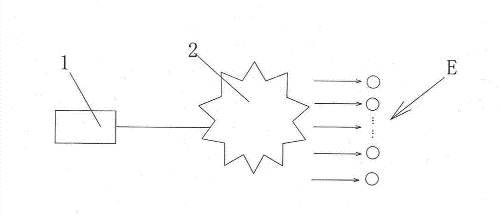
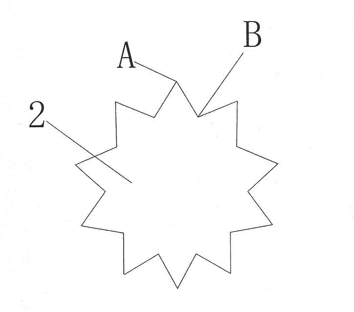
[0023] see figure 2 with image 3 As shown, the energy supply device of the present invention is composed of a signal source 1 and a centrally symmetrical decagonal transmitting coil 2, and the signal source 1 is wired with the centrally symmetrical decagonal transmitting coil 2, and the signal source is a signal generator or RF amplifier. The high-frequency signal generated by the signal source 1 is loaded to the centrally symmetrical decagonal transmitting coil 2 in a wired manner, and then transmitted to the patient wearing the receiving device of the implanted sensor in the form of magnetic resonance wireless power transmission. The energy supply device of the present invention The receiving unit can feed twenty implantable sensors at a time.

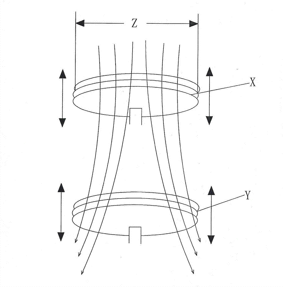
[0024] The present invention calculates the distribution of the magnetic field intensity generated when the centrosymmetric decagonal coil 2 is energized through a shape function obtained by a Fourier transformed Biot-savart rule...


PUM


Abstract

The invention discloses an energy supply device for an implantable sensor and a receiving device of the implantable sensor. The energy supply device consists of a signal source and a centrosymmetric decagonal transmitting coil, wherein the signal source is connected with the centrosymmetric decagonal transmitting coil in a wired manner and is a signal generator or a radio frequency amplifier; and a high-frequency signal generated by the signal source is loaded to the centrosymmetric decagonal transmitting coil in a wired manner, and then is transmitted to a patient wearing the receiving device of the implantable sensor in a magnetic resonance type wireless electric energy transmission mode. According to the energy supply device, energy can be provided for the receiving devices of twenty implantable sensors once; the receiving device consists of a receiving coil, a signal conditioning and rectifying circuit, a sensor part, a transmitting antenna and a biological shell; the receiving coil in the shell is hinged with the shell via a shaft and can rotate around the shaft; and when in work, the energy supply device is passively kept parallel to the transmitting coil since the receiving coil interacts with the centrosymmetric decagonal transmitting coil due to a produced magnetic field, so that maximum receiving efficiency is guaranteed.

Description

technical field [0001] The invention relates to a medical device, in particular to an energy supply device for an implanted sensor and a receiving device for the implanted sensor. Background technique [0002] In 2007, the MIT research team successfully used electromagnetic resonance to light a 60w light bulb at a distance of 2m, and the transmission efficiency was as high as 40%. This experiment uses the basis of electromagnetic induction power transmission, and then uses the principle of magnetic field coupling to greatly improve the transmission efficiency and distance. This technology called witricity has been developed into civilian use in the past few years. [0003] Such as figure 1 As shown in the figure, the power supply Z is applied to both ends of the upper coil X in the figure, and the energized coil generates a magnetic field. When the lower coil Y is close enough to the upper coil X, the magnetic field also passes through the lower coil Y, and the changing mag...

Claims


Application Information

Patent Timeline
Patent Type & Authority Applications(China)
IPC IPC(8): H02J17/00H02J50/12
Inventor 江虹朱小宁韩顺杰付虹李磊
Owner CHANGCHUN UNIV OF TECH
Why Eureka
Try Eureka