Safe separation mechanism used for missile electrical connecting piece

A technology for electrical connectors and safety, which is applied in the direction of electrical components, parts of connecting devices, connections, etc., can solve the problems of large occupied space, high manufacturing cost, inconvenient operation, etc., and achieve low manufacturing cost, easy operation, The effect of simple structure

Pending Publication Date: 2017-12-19
贵州航天风华精密设备有限公司
View PDF9 Cites 2 Cited by
  • Summary
  • Abstract
  • Description
  • Claims
  • Application Information

AI Technical Summary

Problems solved by technology

[0002] With the development of the electric power industry, various electrical products are widely used in various fields of industry and civil use. Electrical connectors are currently the main electrical components used to connect electrical circuits, mainly including power plugs, power terminals, etc. These electrical connections The parts can be connected when they are in use, and they are generally disconnected manually when they are not in use. However, in some military industries and aerospace industries, due to the large shape and structure of the parts, it is necessary to use a larger puller The electrical connection can only be disconnected by force, or because the electrical connection is used in a very dangerous situation, the electrical connection cannot be directly disconnected manually. For example, the electrical connection used on ballistic missiles, in normal times It needs to be turned on so that the vacant circuit on the ballistic missile communicates with the underside launch control system, and when the ballistic missile is launched, it needs to be disconnected even if the electrical connection is separated. Inconvenient, the separation mechanisms used in the prior art for ballistic missile electrical connectors mainly include four-bar linkage separation mechanisms, shear separation mechanisms, electromagnetic separation mechanisms and electric separation mechanisms, etc., and the structures of these separation mechanisms are very complicated , takes up a lot of space, and the manufacturing cost is high. For example, the patent document with the publication number "CN106684638A" discloses a double positioning pin device for connector separation, which includes a front positioning pin, a rear positioning pin, a plug seat, and a connecting pin. The pole electric plug piece and the connecting rod electric plug piece are fixed with a plug seat, and the two ends of the plug seat surface are respectively fixed with a front positioning pin and a rear positioning pin; the front positioning pin includes a first ball head, a first positioning platform, and a first cylindrical section , the first threaded section, the first axis threading hole, the special-shaped guide post, the first cylindrical section and the special-shaped guide post are fixedly connected through the first positioning platform, the special-shaped guide post is provided with a first ball head, and the first cylindrical section is provided with There is a first axis threading hole, and the first cylindrical section is fixedly connected with the first threaded section through the first axis threading hole. Using the device provided by the invention, the lateral separation force when the missile is launched and separated is borne by the double positioning pins, which solves the problem of It solves the problem of damage to the insulating shell of the connector or the bending of the pins, eliminates the potential safety hazard during missile launch, and avoids the risk of launch. However, when the missile is separated, the connector does not maintain a sufficient safety distance after separation. , so there is still a risk of arcing between the electrical connectors after the missile is launched, and there are still some safety hazards

Method used


Image

  • Safe separation mechanism used for missile electrical connecting piece
  • Safe separation mechanism used for missile electrical connecting piece
  • Safe separation mechanism used for missile electrical connecting piece

Examples


Embodiment Construction

[0019] The technical scheme of the present invention will be further described below in conjunction with the accompanying drawings, but the required protection scope is not limited to the description;

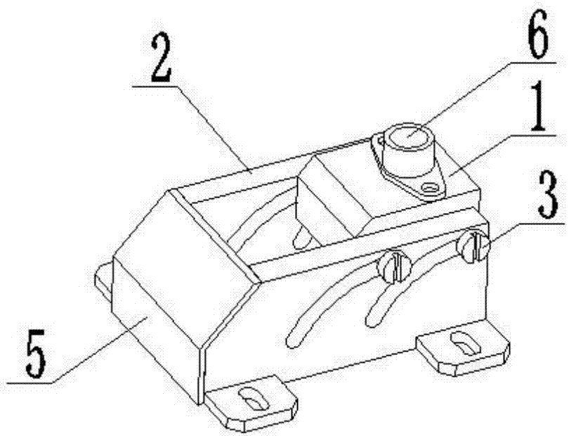
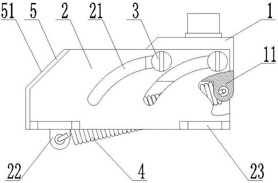
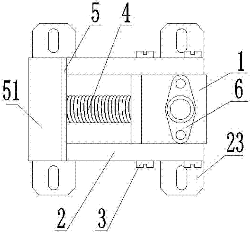
[0020] The present invention provides a safety disengagement mechanism for missile electrical connectors, such as figure 1 , figure 2 , image 3 As shown, it includes a mounting base 1 and a guide plate 2. A separation track 21 is provided on the guide plate 2. Fasteners 3 are provided on both sides of the mounting base 1. The fastener 3 is slidably connected to the separation track 21. Using the technical solution of the present invention, the plug or socket in the electrical connector can be installed on the mounting base 1 using fasteners such as bolts, and is integrated with the mounting base 1. During the storage or transportation of ballistic missiles, the electrical connector remains reliable. ground connection, and when the ballistic missile is launched, the electric...


PUM


Abstract

The invention relates to a safe separation mechanism used for a missile electrical connecting piece. The safe separation mechanism comprises a mounting base and a guiding plate; separated tracks are formed in the guiding plate; fastening parts are arranged on the two sides of the mounting base; and the fastening parts are glidingly connected with the separated tracks. By adoption of the technical scheme provided by the invention, in the storage or transportation process of a ballistic missile, the electrical connecting piece is reliably connected with the mounting base; when the ballistic missile launches, the electrical connecting piece is separated from the mounting base quickly, reliably and automatically; meanwhile, ablation of the electrical connecting piece by hot air flow can be avoided, and enough safe distance is kept between the electrical connecting piece and the ballistic missile, so that launching of the ballistic missile is not affected; and the safe separation mechanism has the advantages of convenience in assembling, simple and convenient operation, simple structure, high reliability, low manufacturing cost and the like, and can be widely applicable to transverse electrical separation mechanisms of various kinds of launching boxes or launching cylinders.

Description

technical field [0001] The invention relates to the technical field of electrical connectors, in particular to a safety release mechanism for missile electrical connectors. Background technique [0002] With the development of the electric power industry, various electrical products are widely used in various fields of industry and civil use. Electrical connectors are currently the main electrical components used to connect electrical circuits, mainly including power plugs, power terminals, etc. These electrical connections The parts can be connected when they are in use, and they are generally disconnected manually when they are not in use. However, in some military industries and aerospace industries, due to the large shape and structure of the parts, it is necessary to use a larger puller The electrical connection can only be disconnected by force, or because the electrical connection is used in a very dangerous situation, the electrical connection cannot be directly disc...

Claims


Application Information

Patent Timeline
Patent Type & Authority Applications(China)
IPC IPC(8): H01R13/633
CPCH01R13/633
Inventor 苏尼锋
Owner 贵州航天风华精密设备有限公司
Why Eureka
Try Eureka