Micro driving motor

A micro-drive and motor technology, applied in the direction of electrical components, electromechanical devices, etc., can solve problems that affect the quality of finished products, errors, etc., and achieve the effect of reducing processing accuracy and process requirements

Inactive Publication Date: 2015-02-11
深圳市光控数码光电有限公司
View PDF3 Cites 0 Cited by
  • Summary
  • Abstract
  • Description
  • Claims
  • Application Information

AI Technical Summary

Problems solved by technology

[0003] Traditional micro drive motors generally include upper cover, upper gasket, upper spring sheet, lens carrier, magnet assembly, coil assembly, lower gasket, lower spring sheet assembly and base; the upper cover of traditional products is bonded to the insulating base by glue The insulating base is bonded to the substrate with glue, and the image sensor is generally placed close to the substrate (usually a circuit board) and parallel to it; in order to ensure the flatness of the upper cover and the substrate, that is, the image sensor, especially the high-pixel lens, the The processing accuracy of the base is required to be high, and regardless of the accuracy requirements of the base, since the upper cover and the base, and the base and the substrate are bonded by glue, an error control will inevitably be introduced, which will affect the quality of the finished product

Method used


Image

  • Micro driving motor
  • Micro driving motor
  • Micro driving motor

Examples


Embodiment 1)

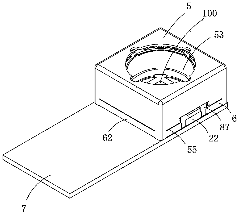
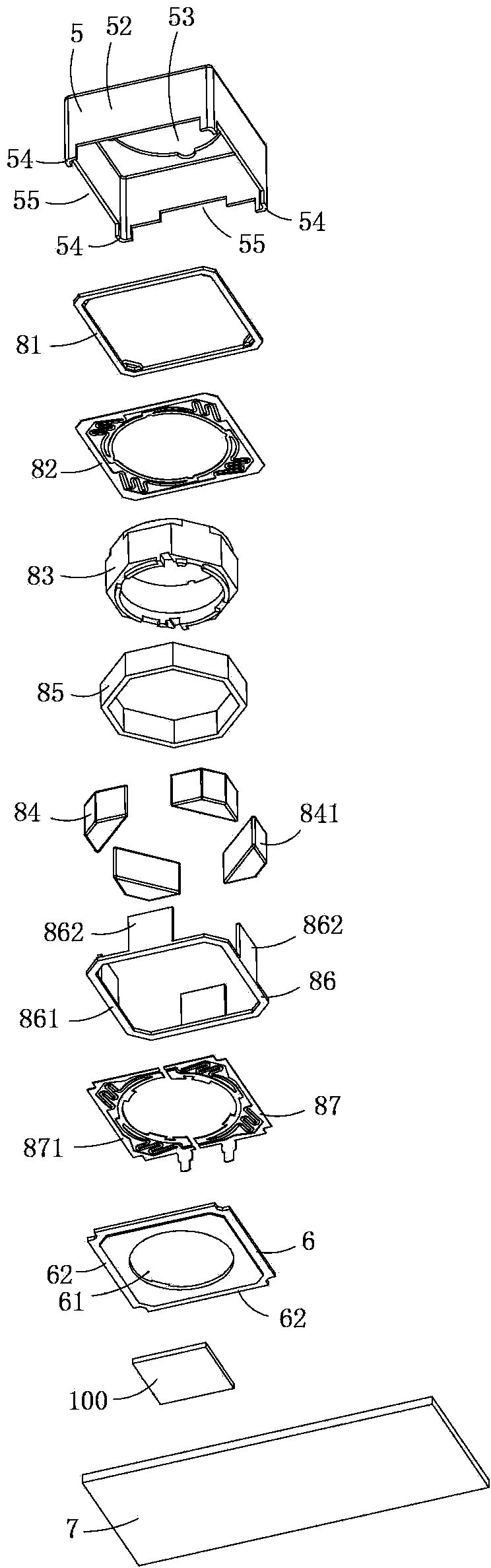
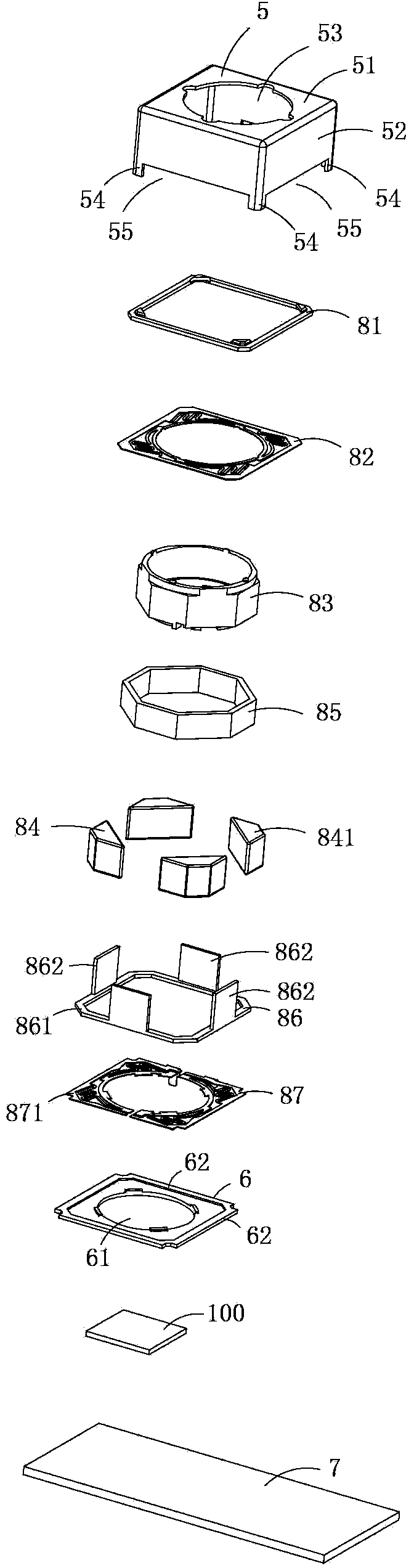
[0017] Figure 1 to Figure 5 A specific embodiment of the invention is shown in which figure 1 It is a schematic diagram of a three-dimensional structure of the present invention; figure 2 yes figure 1 An exploded view of the motor shown; image 3 yes figure 1 An exploded view of the shown motor viewed from another angle; Figure 4 yes figure 1 A schematic diagram of the three-dimensional structure of the upper spring in the motor shown; Figure 5 yes Figure 4 A front view of the upper leaf spring shown.

[0018] The present invention is a kind of miniature driving motor, see Figure 1 to Figure 5 As shown, it includes an upper cover 5, an upper gasket 81, an upper spring piece 82, a carrier 83, a magnet assembly 84 composed of four magnets 841, a coil 85, a lower support member 86, and a lower assembly formed by two lower elastic pieces 871. The shrapnel assembly 87 , the base 6 and the base plate 7 . In order to illustrate this embodiment more clearly, an image s...


PUM


Abstract

The invention discloses a micro driving motor which comprises an upper cover and a base, wherein the upper cover comprises a top wall and a side wall connected with the top wall, and a light hole is formed in the center of the top wall; a center hole is formed in the center of the base; the upper cover further comprises positioning pins, wherein the positioning pins protrude downward from the side wall, and notches are formed among the positioning pins; and connecting parts positioned in all of the notches are arranged on the edge of the base. According to the micro driving motor, the equal-height positioning pins are arranged at the bottom of the upper cover, and the notches are formed among the positioning pins; during installation, the micro driving motor can be directly connected with a base plate in a covered manner by utilizing the equal-height positioning pins, thereby satisfactorily guaranteeing the flatness of the upper cover and the base plate; proper gaps can be left in the position where the bottom wall of the upper cover is matched with the insulating base in the notches, the flatness of the upper cover and the base plate cannot be influenced, and the gaps are filled with glue, so as to bind the upper cover and the base plate; and due to existence of the proper gaps, the requirements on the process precision and the process of the insulating base are effectively reduced.

Description

technical field [0001] The invention belongs to the technical field of micro motors, and in particular relates to a micro drive motor. Background technique [0002] Micro-camera devices have been widely used in mobile phones and notebook computers, and the micro-drive motors (also called lens drive motors) are getting smaller and smaller. [0003] Traditional micro drive motors generally include upper cover, upper gasket, upper spring sheet, lens carrier, magnet assembly, coil assembly, lower gasket, lower spring sheet assembly and base; the upper cover of traditional products is bonded to the insulating base by glue The insulating base is bonded to the substrate with glue, and the image sensor is generally placed close to the substrate (usually a circuit board) and parallel to it; in order to ensure the flatness of the upper cover and the substrate, that is, the image sensor, especially the high-pixel lens, the The processing accuracy of the base is required to be high, an...

Claims


Application Information

Patent Timeline
Patent Type & Authority Patents(China)
IPC IPC(8): H02K33/18
Inventor 夏太红彭全斌
Owner 深圳市光控数码光电有限公司
Why Eureka
Try Eureka