A method for providing power supply, and a power supply device

A technology of a power supply system and a power supply device is applied to the power supply system of a working machine and the module field of the power supply system of a working machine, and can solve problems such as inflexibility and the like

Inactive Publication Date: 2013-05-01
JOHN DEERE FORESTRY INC
View PDF0 Cites 4 Cited by
  • Summary
  • Abstract
  • Description
  • Claims
  • Application Information

AI Technical Summary

Problems solved by technology

However, this approach is not very flexible, since such devices are only suitable for working machines designed for them.

Method used


Image

  • A method for providing power supply, and a power supply device
  • A method for providing power supply, and a power supply device
  • A method for providing power supply, and a power supply device

Examples


Embodiment Construction

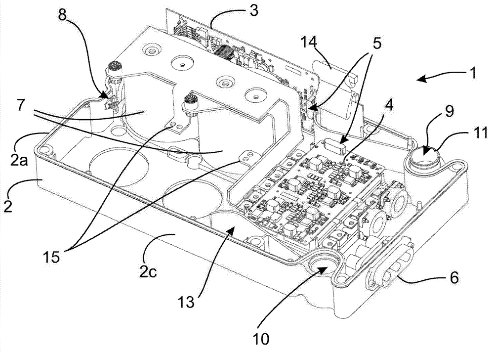
[0026] figure 2 is a perspective view of a power supply 1 according to a preferred embodiment of the present invention. Said power supply 1 advantageously comprises a frame part 2 to which a control unit 3 and other elements enabling the operation of the power supply are connected, including a The output unit 4 of the actuator 27 ( Figure 6 ), and a connecting cable 5, which is used, for example, to electrically connect the control unit 3 and the output unit 4 to each other. The electrical power generated by the power supply 1 is conducted from the output unit 4 to the output connector 6, from which the electrical power can be conducted, eg via cables, to the actuator. In a preferred embodiment of the invention, the frame part 2 simultaneously serves as a cooling element.

[0027] In this specification, elements 3 to 6 that enable the power supply to operate are also referred to as power supply units.

[0028] Some power supplies 1 comprise so-called switched mode power ...


PUM


Abstract

A device (1) has been developed for a power supply system of a working machine (26), for supplying electric power to at least one actuator (27a-27c). The device (1) comprises a frame part (2) with a bottom (2b). The device (1) comprises a cooling liquid channel system (9, 10), and the frame part (2) comprises a recess (16) which can be arranged in a flow connection with said cooling liquid channel system (9, 10). The devices can be combined to form modules for the power supply system of the working machine (26), for supplying electric power to at least one actuator (27a-27c), wherein a module (12) comprises two devices (1 a, 1b) placed against each other. The power supply system of the working machine (26) can be composed of the modules.

Description

technical field [0001] The invention relates to a device for a power supply system of a working machine for supplying electrical power to at least one actuator, said device comprising a frame part with a base and an edge. The invention also relates to a module of a working machine power supply system and a working machine power supply system. Background technique [0002] Various power supplies are known that can be used to provide power to electric actuators, such as electric motors, pumps, lighting, measuring devices, and the like. One goal of a power supply is to provide conversion of electrical power into a form that can be used in electrically operated devices. For example, the voltage from the power source does not match the operating voltage required by the working device, and the power supply can convert the voltage from the power source into a voltage suitable for the working device. On the other hand, the voltage from the power source can be an alternating curren...

Claims


Application Information

Patent Timeline
Patent Type & Authority Applications(China)
IPC IPC(8): H02M1/00H05K7/20
CPCH05K7/20927H05K7/20218Y02T10/70Y02E60/10H01M10/613B60L50/66B60R16/0238H02J4/00
Inventor 奥利·汉卡马基
Owner JOHN DEERE FORESTRY INC
Why Eureka
Try Eureka