Heat sink and assembly method thereof

A technology of a heat dissipation device and an assembly method, applied in the direction of cooling/ventilation/heating transformation, can solve the problem of heat dissipation effect, the inability of the heat dissipation device to effectively remove dust, etc., to achieve an increase in the area for absorbing heat, good heat conduction effect, and increase heat dissipation effect. Effect

Active Publication Date: 2016-12-14
GIGA BYTE TECH CO LTD
View PDF12 Cites 0 Cited by
  • Summary
  • Abstract
  • Description
  • Claims
  • Application Information

AI Technical Summary

Problems solved by technology

[0011] In view of this, the present invention provides a heat dissipation device and an assembly method thereof, thereby solving the problem of the heat dissipation effect of the conventional heat dissipation device and the ineffective dust removal problem of the conventional heat dissipation device

Method used


Image

  • Heat sink and assembly method thereof
  • Heat sink and assembly method thereof
  • Heat sink and assembly method thereof

Examples


Embodiment Construction

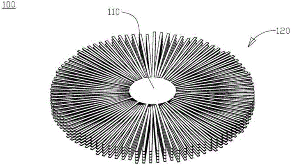
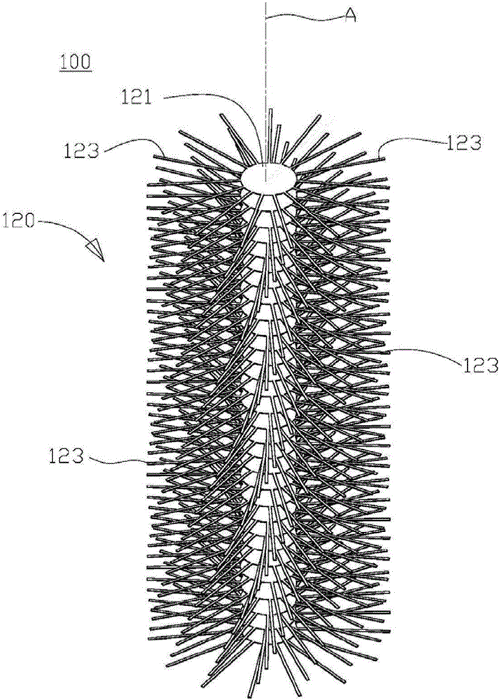
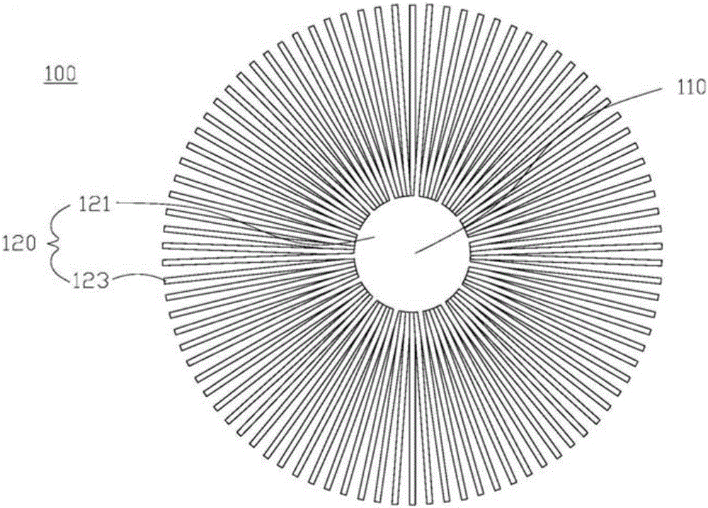
[0062] Please refer to figure 1 The three-dimensional schematic diagram of the cooling device of the first embodiment of the present invention is shown, and please refer to figure 2 The exploded schematic view of the heat sink of the first embodiment of the present invention shown, and Figure 23 Shown is a flow chart of the steps of the heat dissipation device according to the first embodiment of the present invention.

[0063] The heat dissipation device 100 includes a plurality of heat dissipation plates 120, wherein each heat dissipation plate 120 is stacked in sequence along an axial direction A (such as Figure 23 set forth in step 500). Furthermore, each cooling plate 120 includes a fixing portion 121 and a plurality of fin strips 123 . Wherein, the fixing portion 121 is generally in the form of a ring-shaped solid sheet structure, so it has a certain area, but the appearance of the fixing portion 121 is not limited to the one disclosed in this embodiment. In addit...


PUM


Abstract

The invention relates to a heat dissipation device comprising a plurality of heat dissipation plates, each heat dissipation plate is stacked along an axial direction. Each cooling plate includes a fixing part and a plurality of fin strips, each cooling plate is stacked and combined with each other by the fixing part, and each fin strip is arranged on the outer edge of the fixing part at intervals. The heat dissipation device with the above structure can achieve better heat dissipation effect and dustproof effect.

Description

【Technical field】 [0001] The present invention relates to a heat dissipation device, in particular to a heat dissipation device composed of a plurality of heat dissipation plates with a plurality of fin strips stacked and arranged and an assembly method thereof. 【Background technique】 [0002] The application of electronic products has penetrated into all aspects of production and life in today's society, and its system performance and user experience are directly related to social production efficiency and people's quality of life. Computers occupy an important position in the field of electronic products. The electronic components in the computer will generate heat when they are running. The high-heating electronic components must be equipped with cooling devices to keep their operating temperature within the allowable range. If the operating temperature is too high, their performance will deteriorate or even fail. The heat-generating components that need heat dissipation...

Claims


Application Information

Patent Timeline
Patent Type & Authority Patents(China)
IPC IPC(8): H05K7/20
Inventor 黄顺治毛黛娟
Owner GIGA BYTE TECH CO LTD
Why Eureka
Try Eureka