Guidewire

A technology of guide wire and coil, applied in the direction of guide wire, etc., can solve the problems of inability to transmit, poor wettability, and detachment of coil wire, etc., and achieve the effects of preventing detachment, improving torque transmission, and reliable tightening

Inactive Publication Date: 2013-05-08
ASAHI INTECC CO LTD
View PDF2 Cites 15 Cited by
  • Summary
  • Abstract
  • Description
  • Claims
  • Application Information

AI Technical Summary

Problems solved by technology

[0009] However, since the guide wire described in Patent Document 1 includes a distal end coil with low bending rigidity formed by twisting a plurality of wires, and a proximal coil formed by winding a single wire, it has the problem of easily generating a distal end. Due to the difference in rigidity between the front and back of the joint between the coil and the proximal coil, the joint becomes a starting point of stress concentration when torque is transmitted from the proximal end of the guide wire to the distal end, and the torque at the proximal end of the guide wire cannot be fully controlled. to the tip of the guidewire
[0010] In addition, although the guide wire described in Cited Document 2 uses tungsten for the coil wire, tungsten is a metal with poor wettability with metal solder, so it is a material that is difficult to braze, and because it is a metal with a high melting point, it is It is a material that is difficult to weld with other parts, so the bonding of the second wire made of tungsten and the first wire, and the bonding of the coil wire containing tungsten and the core wire cannot be performed sufficiently, and there is a danger of the coil wire detaching from the core wire

Method used


Image

  • Guidewire
  • Guidewire
  • Guidewire

Examples


no. 1 approach >

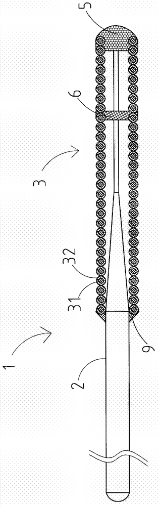
[0031] figure 1 It is an overall view showing the guide wire 1 according to the first embodiment of the present invention.

[0032] In addition, in figure 1 In the description, for convenience of description, the left side is referred to as the "proximal side" and the right side is described as the "tip side".

[0033] In addition, in figure 1 In FIG. 2 , the longitudinal direction of the guide wire 1 is shortened and the whole is schematically shown for easy understanding, so the overall size is different from the actual size.

[0034] exist figure 1 Among them, the guide wire 1 includes: a mandrel 2; a coil body 3 covering the front end of the mandrel 2; In the proximal direction of the front end portion 5 , the coil body 3 and the mandrel 2 are fastened by the intermediate fastening portion 6 , and the proximal end of the coil body 3 and the mandrel 2 are fastened by the proximal fastening portion 9 .

[0035] Furthermore, the front end portion 5 , the intermediate fas...

no. 2 approach >

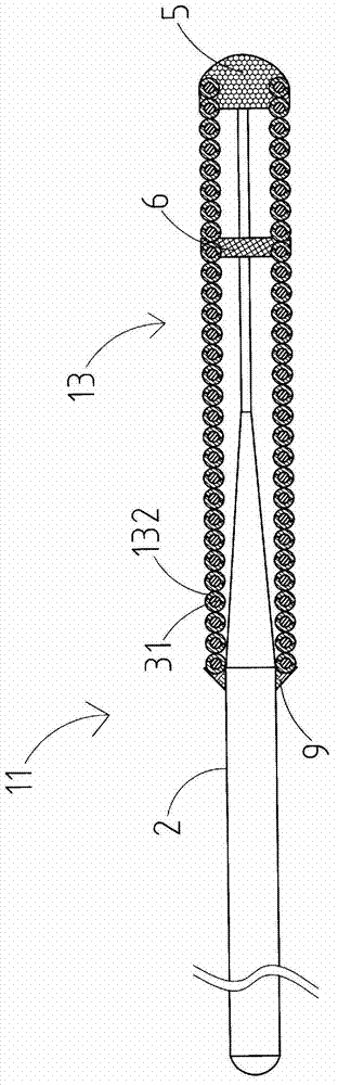
[0059] Below, use figure 2 , the guide wire 11 of the second embodiment will be described focusing on differences from the first embodiment. The same reference numerals are assigned to the same parts as in the first embodiment in the drawings.

[0060] Also, for ease of understanding, figure 2 The length direction of the guide wire 11 is shortened, and the whole of the guide wire 11 is schematically shown, so the overall size is different from the actual size.

[0061] exist figure 2 Among them, the coil wire material of the coil body 13 of the guide wire 11 includes a core wire 31 composed of a tungsten wire, and a side wire 132 composed of two stainless steel wires wound so as to cover the outer periphery of the core wire 31, except the above-mentioned Other than this point, it has the same form as 1st Embodiment.

[0062] In this way, in the guide wire 11 of the second embodiment, the coil wire material of the coil body 13 includes a core wire 31 composed of one tung...

no. 3 approach >

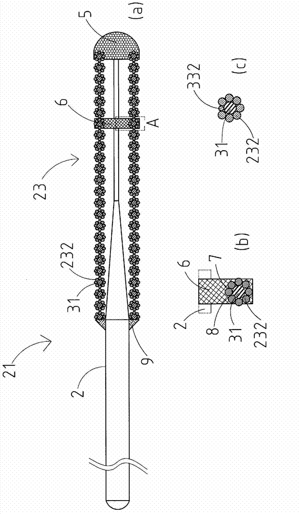
[0065] Second, use image 3 (a), image 3 (b) and image 3 (c) The guide wire 21 of the third embodiment will be described focusing on the differences between the first embodiment and the second embodiment. The same symbols are assigned to the same parts as those of the first embodiment and the second embodiment in the drawings.

[0066] Also, for ease of understanding, image 3 (a) The longitudinal direction of the guide wire 21 is shortened, and the entire guide wire 21 is schematically shown, so the overall size is different from the actual size. in addition, image 3 (b) is enlarged image 3 (a) A diagram of part A, image 3 (c) means image 3 (b) is a diagram of a modified example of the coil wire of the coil body.

[0067] exist image 3 (a) and image 3 In (b), for the guide wire 21 , the coil wire material of the coil body 23 includes a core wire 31 made of one tungsten wire, and eight stainless steel wires wound so as to cover the outer circumference of the ...


PUM


Abstract

The invention provides a guidewire, which can make sure bonding strength between a coil and a core shaft containing tungsten having bad wettability with brazing metal, and can enhance torque transmission performance. The guidewire (1) includes a core shaft (2) and a coil body (3) that covers the core shaft (2). The guidewire also includes a tip portion, an intermediate fixing portion, and a proximal-end fixing portion that fix the core shaft (2) and the coil body (3) to each other. The coil body (3) includes a single core wire formed of a tungsten wire and a single side wire formed of a stainless steel wire. The side wire is wound around the core wire so as to cover the outer periphery of the core wire.

Description

technical field [0001] The present invention relates to guide wires. Background technique [0002] Conventionally, various guide wires have been proposed for insertion into tubular organs such as blood vessels, alimentary canals, and urinary catheters, or tissues in the body to guide medical devices to target sites. [0003] For example, with regard to the guide wire described in Patent Document 1, the distal coil is formed in a helical spring form by twisting a plurality of wires, and the proximal coil is formed in a helical spring form by a single wire, thereby realizing the front end of the guide wire. Both softness and torque transmission are taken into account. [0004] In addition, the coil wire of the guide wire described in Patent Document 2 is formed of a first wire and a second wire, the front end portion of the first wire is made of a radiation-opaque material, and the other part is made of a radiation-transmissive high-elastic material. The entire second wire i...

Claims


Application Information

Patent Timeline
Patent Type & Authority Applications(China)
IPC IPC(8): A61M25/09
CPCA61M2025/09083A61M2025/09166A61M25/09
Inventor 宫田尙彦松尾一美坂仓亚希
Owner ASAHI INTECC CO LTD
Why Eureka
Try Eureka