Cutting tool structure based on rolling anti-attrition principle

A cutting tool, rolling and anti-friction technology, applied in the direction of tools for lathes, turning equipment, manufacturing tools, etc., to achieve the effect of improving quality, reducing cutting temperature, and improving cutting performance

Inactive Publication Date: 2013-05-08
SHANGHAI JIAO TONG UNIV
View PDF7 Cites 8 Cited by
  • Summary
  • Abstract
  • Description
  • Claims
  • Application Information

AI Technical Summary

Problems solved by technology

From the perspective of wear reduction mechanism, the tool structure is currently improved based on the principle of rolling wear reduction to reduce the friction between the traditional "chip-tool-machined surface" based on the principle of sliding friction, thereby improving the cutting performance of the tool and Tools for machining surface integrity have not yet been covered

Method used


Image

  • Cutting tool structure based on rolling anti-attrition principle
  • Cutting tool structure based on rolling anti-attrition principle
  • Cutting tool structure based on rolling anti-attrition principle

Examples


Embodiment

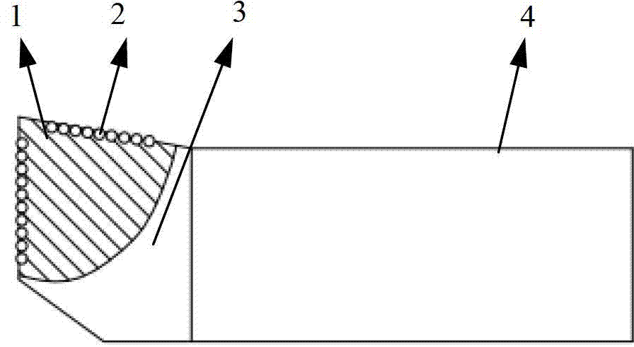
[0019] Such as Figure 1~4 As shown, a cutting tool structure based on the principle of rolling wear reduction includes an integrated cutter body 4 and a cutter head 3, the rake face and flank face of the cutter head are provided with microgrooves 1, microgrooves 1 The depth gradually decreases along the direction away from the tool tip. The microgroove 1 is formed by arranging a plurality of microholes, each microhole is embedded with a ball 2, the diameter of the ball 2 is slightly smaller than the diameter of the microhole, and can roll freely in the microhole.

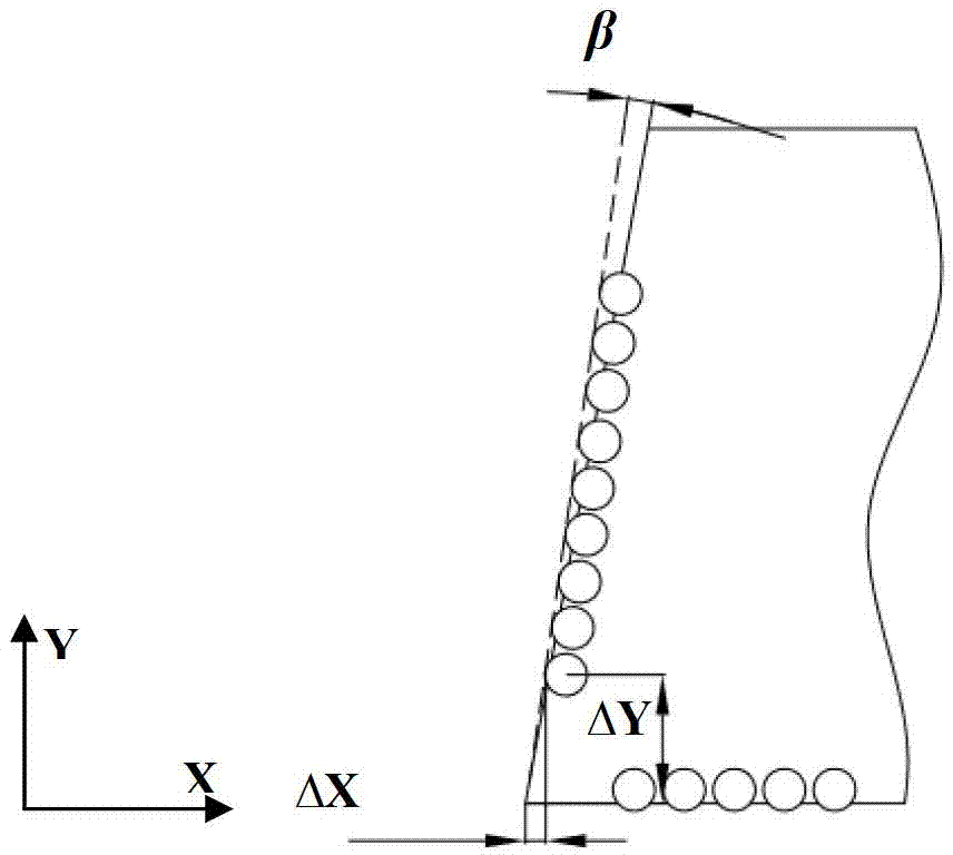
[0020] Such as figure 2 As shown, the distances of the ball closest to the tool tip in the X and Y directions are ΔX and ΔY, respectively, ΔX=0.5-5mm and ΔY=0.5-2mm. On the one hand, it is to ensure that the tool tip contacts the workpiece first during cutting, and on the other hand, to prevent the tool tip from breaking, it is necessary to keep a certain distance between the first ball and the tool tip. The de...

Embodiment 2

[0023] The micro-groove is groove-shaped, and the distances from the end of the micro-groove to the tip of the knife in the X and Y directions are ΔX and ΔY respectively, ΔX=0.5mm and ΔY=2mm. All the other are with embodiment 1.


PUM


Abstract

The invention relates to a cutting tool structure based on a rolling anti-attrition principle. The cutting tool structure comprises a cutting body (4) and a cutting head (3) which are arranged integrally. Microgrooves (1) are arranged in the front cutting face and the rear cutting face of the cutting head, and balls (2) are arranged inside the microgrooves in an embedding mode. Compared with the prior art, the cutting tool structure based on the rolling anti-attrition principle can improve the precision of a finished surface, reduce frictional work generated by sliding friction in traditional, so that cutting heat is reduced, and the physical performance of the surfaces of machining workpieces is improved. Cutting tools of the cutting toll structure are strong in generality, good in cutting performance, long in service life, and high in quality of the finished surface.

Description

technical field [0001] The invention relates to a cutting tool structure, in particular to a cutting tool structure based on the principle of rolling wear reduction. Background technique [0002] In the process of metal cutting, the front and flank surfaces of the tool continue to have sliding friction with the workpiece, causing the temperature in the contact area to rise sharply, causing the tool to fail quickly due to friction and wear, thereby reducing the cutting efficiency and the surface integrity of the workpiece. Therefore, it is very important to reduce the friction between the rake face of the tool and the chip, the flank face and the machined surface of the workpiece to improve the cutting performance of the tool and the surface quality of the machined parts. [0003] At present, there are two main methods to improve the cutting performance of cutting tools. One is to develop new cutting tool materials and coating technologies to enhance the wear resistance and h...

Claims


Application Information

Patent Timeline
Patent Type & Authority Applications(China)
IPC IPC(8): B23B27/00
Inventor 张雪萍丁利强孟龙
Owner SHANGHAI JIAO TONG UNIV
Why Eureka
Try Eureka