Locking structure of automobile seat sliding rail

A technology of a car seat slide rail and locking structure, which is applied in directions such as movable seats, can solve the problems of high cost and large space occupied by the locking mechanism, and achieve the effects of improving longitudinal strength, increasing space utilization, and reducing thickness

Active Publication Date: 2013-05-08
WUXI HAIDAER PRECISION SLIDES CO LTD
View PDF6 Cites 4 Cited by
  • Summary
  • Abstract
  • Description
  • Claims
  • Application Information

AI Technical Summary

Problems solved by technology

[0003] In view of the above problems, the present invention provides a locking structure for the slide rail of a car seat, which can solve the problems of lar

Method used


Image

  • Locking structure of automobile seat sliding rail
  • Locking structure of automobile seat sliding rail
  • Locking structure of automobile seat sliding rail

Examples


Embodiment Construction

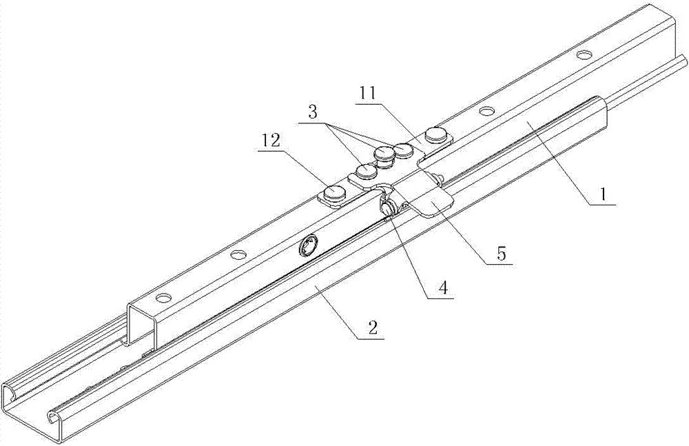
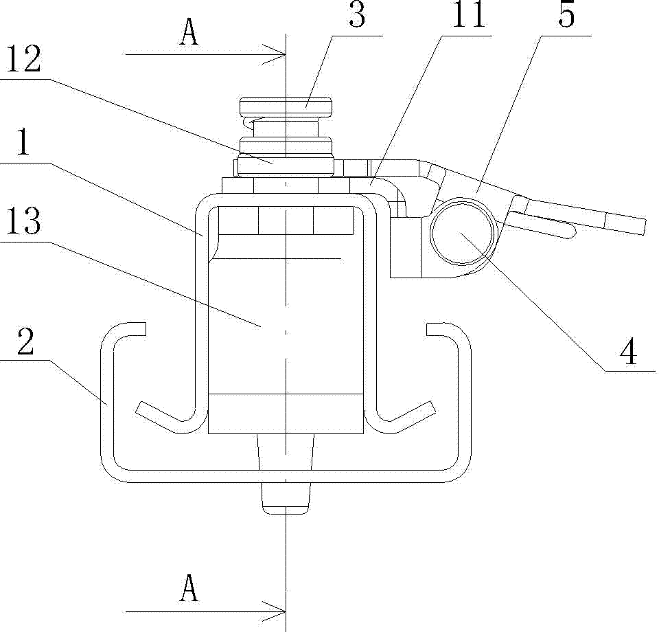
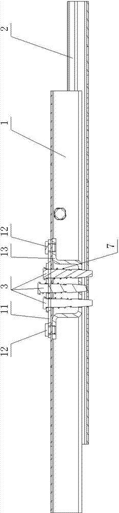
[0013] See Figure 4 , Figure 5 with Image 6 , the present invention includes an upper slide rail 1, a lower slide rail 2, a locking pin 3, a shaft pin 4 and an unlocking drive plate 5, the upper slide rail 1 is installed in the lower slide rail 2, and the upper slide rail 1 can The lower rail 2 moves back and forth horizontally, the lower rail 2 has a locking hole (not shown in the figure), the upper rail 1 is installed with a pin mounting bracket 6, and the locking pin 3 passes through the upper slide from top to bottom Rail 1, column pin mounting bracket 6, locking column pin 3 is connected and installed with column pin return spring 7, unlocking drive plate 5 is installed on shaft pin 4 through unlocking and driving return spring 8, and shaft pin 4 is installed on the upper side through support plate 9 On the slide rail 1 , the front bayonet of the unlocking drive plate 5 is engaged with the locking pin, and the support plate 9 is fixedly mounted on one side of the upp...


PUM


Abstract

The invention provides a locking structure of an automobile seat sliding rail. The locking structure of the automobile seat sliding rail solves the problems that an existing locking structure is large in occupied space and high in cost, and improves utilization rate of a vertical space of a sliding rail. The locking structure of the automobile seat sliding rail comprises an upper sliding rail, a lower sliding rail, locking pins, a shaft pin and an unlocking driving plate, wherein the upper sliding rail is installed in the lower sliding rail and can move horizontally and frontward and backward in the lower sliding rail under unlocking condition, locking holes are formed in the lower sliding rail, a pin installing support is installed in the upper sliding rail, the locking pins penetrate through the upper sliding rail and the pin installing support from top to bottom, pin return springs are connected and installed on the periphery of the locking pins, the unlocking driving plate is installed on the shaft pin through an unlocking driving return spring, the shaft pin is installed on the upper sliding rail through a supporting plate, and a front end bayonet of the unlocking driving plate is connected with the locking pins in a clamped mode. The locking structure of the automobile seat sliding rail is characterized in that the supporting plate is fixedly installed on one side face of the upper sliding rail through a bolt.

Description

technical field [0001] The invention relates to the field of car slide rail structures, in particular to a locking structure of car seat slide rails. Background technique [0002] In the field of automobiles, in order to adapt to the occupants of different sizes, so that the occupants can drive and ride in the car more comfortably and reduce driving fatigue, a guide rail that can be adjusted front and rear or left and right is usually installed under the car seat, and the locking structure will The upper slide rail and the lower slide rail are locked, and the locking structure ensures the safe and reliable positioning of the car seat, which needs to ensure that the upper slide rail and the lower slide rail can still be reliably locked when the car is subjected to a severe impact. Now with locking structure, see figure 1 , figure 2 with image 3 , which includes a locking pin 3, a shaft pin 4 and an unlocking drive plate 5, the unlocking driving plate 5 is installed on th...

Claims


Application Information

Patent Timeline
IPC IPC(8): B60N2/08
Inventor 陆斌武
Owner WUXI HAIDAER PRECISION SLIDES CO LTD
Why Eureka
Try Eureka