Tension device for weaving carbon fibers

A tension device and carbon fiber technology, applied in the direction of fabrics, textiles, looms, etc., can solve the problems of serious hairiness on the surface of carbon fiber bundles, carbon fiber hairiness blocking the warp yarn channel, and affecting the warp yarn density. Fatigue and damage tolerance, effects of improving planar strength

Inactive Publication Date: 2012-06-27
XIAN KANGBEN MATERIAL
View PDF3 Cites 4 Cited by
  • Summary
  • Abstract
  • Description
  • Claims
  • Application Information

AI Technical Summary

Problems solved by technology

This kind of warp tension adjustment is more suitable for all kinds of chemical fibers or cotton threads. Due to the influence of carbon fiber itself, this method will lead to (a) serious hairiness on the surface of carbon fiber bundles, which will affect the linear density of warp yarns; (b) part of warp yarns in sheet warp yarns The tension of the tow is inconsistent, and the warp color difference appears on the surface of the carbon fiber cloth
Due to the above problems, it is easy to fluff carbon fiber during weaving, and it is easy to cause carbon fiber hairiness to bloc...

Method used


Image

  • Tension device for weaving carbon fibers
  • Tension device for weaving carbon fibers
  • Tension device for weaving carbon fibers

Examples


Embodiment Construction

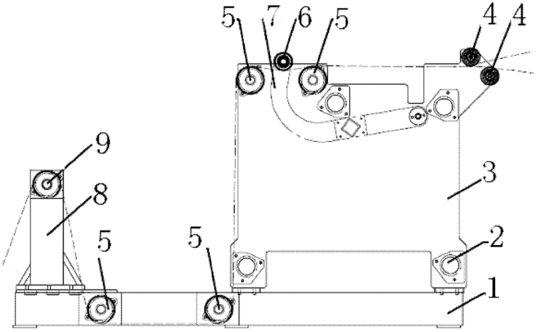
[0028] This embodiment is a warp tension mechanism for carbon fiber weaving.

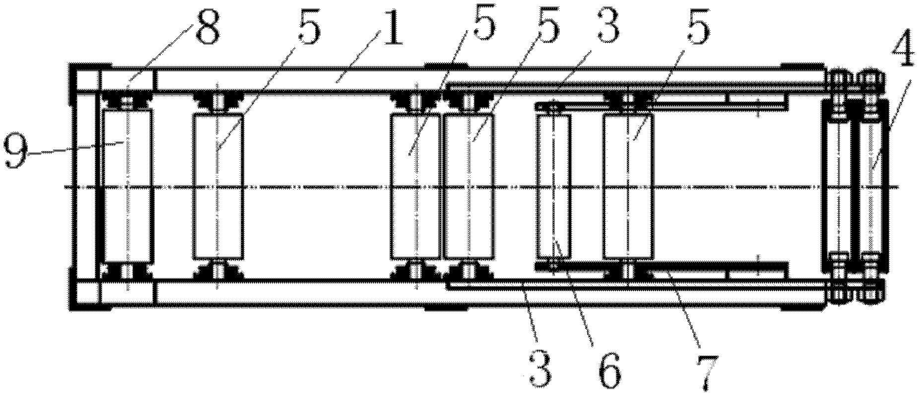
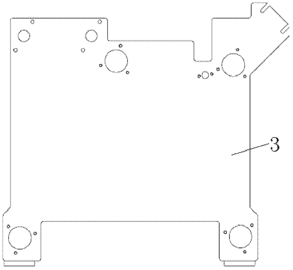
[0029] Such as figure 1 shown. The longitudinal tension mechanism of this embodiment includes a support 1, four frame cross braces 2, a pair of wall panels 3, a pair of rear guide rollers 4, four intermediate guide rollers 5, a tension roller 6, and a swing arm 7 , front support 8, leading yarn roller 9.

[0030]The support 1 is the carrier of this embodiment, and is a rectangular frame welded by channel steel. A pair of wall panels 3 are respectively fixed on the upper surface of one end of the two long sides of the support 1, and are fixed with bolts by four frame cross braces 2 to form a support frame. A pair of rear yarn guide rollers 4 are respectively fixed in the mounting grooves of the rear yarn guide rollers 4 at one end of the wallboard; one rear yarn guide roller in the pair of rear yarn guide rollers 4 is located at the other rear yarn guide roller. above the roller, and the lower ci...


PUM


Abstract

The invention relates to a tension device for weaving carbon fibers. A pair of rear yarn guide rollers is vertically arranged at one end of one wallboard and one end of the other wallboard, and an included angle is formed between the centers of the two yarn guide rollers; four middle yarn guide rollers are divided into two groups and respectively arranged on the wallboards and a support; a pair of swing arms is hinged to the wallboards; a tension roller is arranged at the tension roller mounting end of each swing arm through a bearing; when the mounting end of each swing arm moves to the upper surface of a support frame consisting of a pair of wallboards, the tension roller is positioned between a group of middle yarn guide rollers, and the lower circumferential surface of the tension roller and the upper circumferential surfaces of the group of middle yarn guide rollers are positioned on the same horizontal plane; and a pair of front support plates is fixed on the upper surface of one end of the support. The warp tension of the woven carbon fiber bidirectional cloth is uniform, platy macroscopic tension is 20 percent of breaking strength of a carbon fiber strand, an error is +/-2 percent, the warp texture fiber strength of the carbon fiber cloth is effectively improved, fatigue and damage tolerance is enhanced, cost is reduced, and the aim of reducing the whole weight is fulfilled.

Description

technical field [0001] The invention relates to the field of preparation of carbon fiber downstream products, in particular to a mechanism for realizing warp tension of polyacrylonitrile-based carbon fiber weaving. In particular, it involves the weaving of carbon fiber cloth woven from continuous carbon fiber for aircraft, aerospace, aviation and other aircraft, transportation, building materials and weaponry. Background technique [0002] Carbon fiber has a series of excellent properties such as high specific strength, high specific modulus, fatigue resistance, creep resistance, corrosion resistance and small thermal expansion coefficient, so it is widely used in carbon fiber reinforced resin matrix composite materials ( CFRP) is a reinforcement, and it is also a new material for the upgrading of the civil industry. Carbon fiber cloth is the preliminary product of carbon fiber. Generally, carbon fiber cloth is required to have (a) high specific strength and large specific ...

Claims


Application Information

Patent Timeline
IPC IPC(8): D03D49/06D03D15/00D03D15/275
Inventor 杨建恒刘红卫许东张鹏郑桂宁
Owner XIAN KANGBEN MATERIAL
Why Eureka
Try Eureka