Front-mounted blowing structure bunching component

A clustering and component technology, applied in the direction of textiles and papermaking, fiber processing, combing machines, etc., can solve the problems of easy hanging, low efficiency, insufficient cotton web attraction, etc., and achieve short bundling time, easy implementation, and simple structure Effect

Inactive Publication Date: 2013-05-08
JIANGSU TAIDA TEXTILE
View PDF0 Cites 3 Cited by
  • Summary
  • Abstract
  • Description
  • Claims
  • Application Information

AI Technical Summary

Problems solved by technology

The deficiencies of the prior art are: on the one hand, the position where air is blown from the air inlet hole on the upper end surface of the cluster body to the inner hole of the guide bar tube is located at the right end orifice of the bar tube, and the distance from the small end of the tapered groove on the cluster body is relatively small. Short, when blowing air, most of the airflow enters the inner hole of the guide tube and flows to the left of the guide tube joint, and a small part of the air flows to the right end of the straight hole connecting the guide tube on the cluster; on the other hand, the The curved part forms a certain resistance to the airflow flowing into the inner hole of the guide tube. These two factors make the negative pressure generated at the right end of the straight hole connected to the guide tube on the cluster body smaller, and the negative pressure on the conical groove on the cluster body The attraction force generated by the cotton net is insufficient, and the opening at the right end of the straight hole connected to the guide tube on the cluster body is easy to hang and block, and it takes a long time to gather and bundle the cotton net, and the efficiency is low

Method used


Image

  • Front-mounted blowing structure bunching component
  • Front-mounted blowing structure bunching component
  • Front-mounted blowing structure bunching component

Examples


Embodiment Construction

[0015] The present invention will be further described below according to the drawings and in combination with the prior art and the embodiments of the present invention.

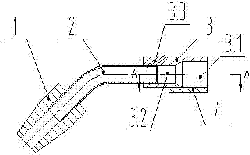
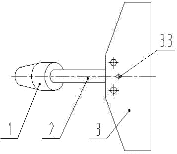
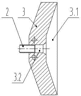
[0016] Such as figure 1 , figure 2 , image 3 Shown is the pre-blowing structure cluster assembly of the prior art, which includes a cluster body 3, a guide tube 2, a guide tube joint 1, and a lower supporting plate 4; the cluster body 3 is a flat block member, and the longitudinal flat The lower right part of the cluster 3 is provided with a groove 3.1 opening to the right and downward, and the shape in the horizontal section of the groove 3.1 is a taper with the large end facing to the right; The straight hole 3.2 communicated with the tapered small end of the groove 3.1, the right end of the guide tube 2 is inserted into the straight hole 3.2 of the cluster 3, and is sealed and connected; the left end of the guide tube 2 is bent to the lower left, and the guide The tube joint 1 is set on the left...


PUM


Abstract

The invention discloses a front-mounted blowing structure bunching component. The front-mounted blowing structure bunching component comprises a bunching body, a strip guide tube, a strip guide tube joint and a lower supporting plate, the bunching body is a flat bulk member, a conical groove with a rightward large end is arranged on the lower right portion of the bunching body which is longitudinally and flatly arranged, a right end of the strip guide tube is connected with a straight hole of the bunching body in a sealing mode, a tube opening at a left end of the strip guide tube is leftwards and downwards bent, the strip guide tube joint is sleeved on the tube opening at the left end of the strip guide tube, and an air inlet hole is mounted on the upper end face of the bunching body. The front-mounted blowing structure bunching component is characterized in that an inclined hole which is communicated with an inner hole of the strip guide tube joint is arranged on the right end face of the strip guide tube joint, a blowing tube is mounted, a right end of the blowing tube is connected with the air inlet hole on the bunching body in the sealing mode, and a left end of the blowing tube is connected with the inclined hole on the right end face of the strip guide tube joint in the sealing mode. According to the front-mounted blowing structure bunching component, a blowing structure is front-mounted, large negative pressure is generated in the inner hole of the strip guide tube to form a large attraction force, hitching and blocking phenomena at a hole opening at the right end of the straight hole of the bunching body connected with the strip guide tube can be prevented, cotton-fleece retracting and bunching time is short, and cotton-fleece retracting and bunching efficiencies are high.

Description

technical field [0001] The invention belongs to the technical field of textile machinery, and relates to a bunching assembly for gathering and bunching cotton webs in the drafting part of a cotton combing machine. Background technique [0002] The bundle assembly in the drafting part of the existing cotton combing machine is used to gather and bundle the cotton web to form a sliver. As for the block member, the lower right part of the longitudinally flat cluster is provided with a groove opening to the right and downward, and the shape of the horizontal section of the groove is a cone with the large end facing to the right; in the middle of the left end surface of the groove There is a straight hole communicating with the tapered small end of the groove, the right end of the guide tube is inserted into the straight hole of the cluster, and is sealed and connected; the left end of the guide tube bends to the lower left, and the guide tube joint is set The nozzle at the left ...

Claims


Application Information

Patent Timeline
Patent Type & Authority Applications(China)
IPC IPC(8): D01G19/14
Inventor 李顺喜黄智鹏王跃明唐建美
Owner JIANGSU TAIDA TEXTILE
Why Eureka
Try Eureka