Three-valve hot-air engine

A hot gas engine and cylinder technology, which is applied to hot gas variable capacity engine devices, machines/engines, mechanical equipment, etc., can solve problems such as heat loss and low fuel efficiency

Inactive Publication Date: 2013-05-08
ZEROQ SCI & TECH
View PDF10 Cites 2 Cited by
  • Summary
  • Abstract
  • Description
  • Claims
  • Application Information

AI Technical Summary

Problems solved by technology

[0002] Traditional internal combustion engines generally discharge high-temperature exhaust gas directly, resulting in serious heat loss
However, the gas working medium in the traditional heat engine needs heat to heat, and the conventional heating method is external combustion, and the fuel usage efficiency is low. Engines for further utilization of waste heat from engine exhaust

Method used


Image

  • Three-valve hot-air engine
  • Three-valve hot-air engine
  • Three-valve hot-air engine

Examples


Embodiment 1

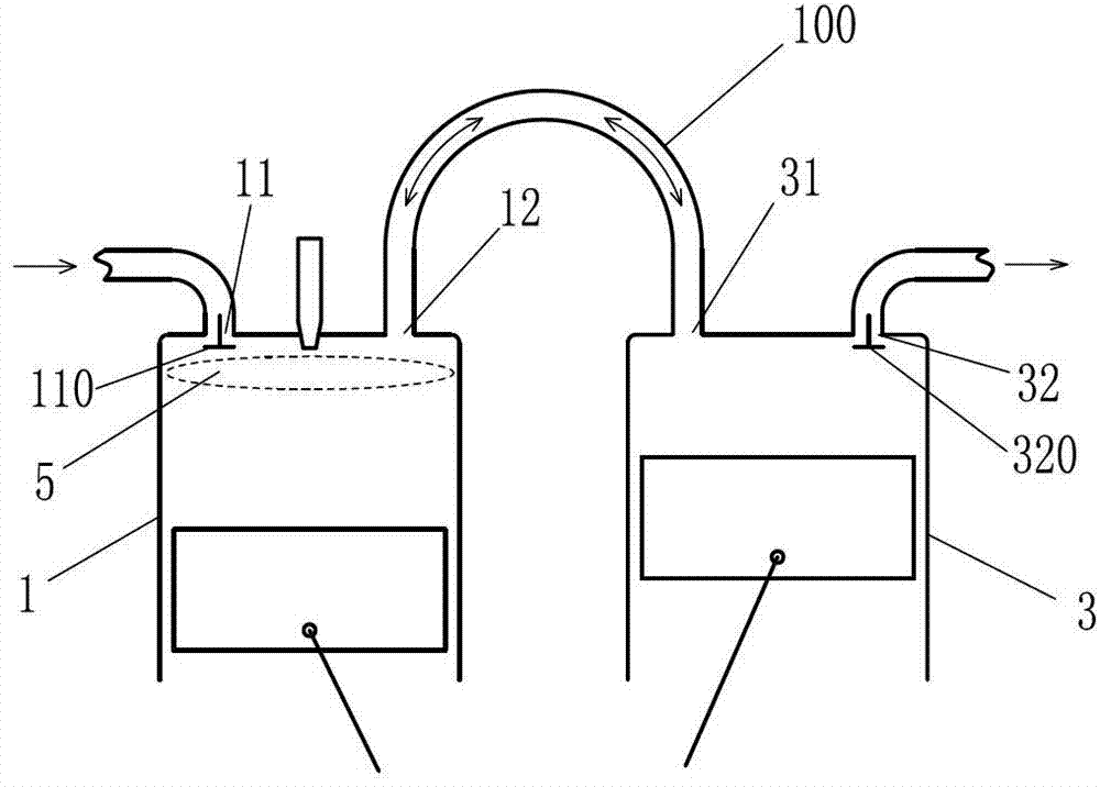
[0093] Such as figure 1 The three-type door hot gas engine shown includes a cylinder-piston mechanism 1 and an auxiliary cylinder-piston mechanism 3. The cylinder of the cylinder-piston mechanism 1 is provided with an air inlet 11 and a reciprocating flow port 12, and the air inlet 11 is provided with There is a corresponding intake valve 110, and the cylinder of the cylinder-piston mechanism 1 is provided with a combustion chamber 5; the cylinder of the auxiliary cylinder-piston mechanism 3 is provided with an auxiliary reciprocating flow port 31 and an exhaust gas discharge port 32. A corresponding exhaust valve 320 is provided at the exhaust port 32 ; the reciprocating flow port 12 communicates with the auxiliary reciprocating flow port 31 through the reciprocating communication channel 100 .

[0094] The intake valve 110 on the cylinder of the cylinder-piston mechanism 1 and the exhaust valve 320 on the cylinder of the auxiliary cylinder-piston mechanism 3 are all control...

Embodiment 2

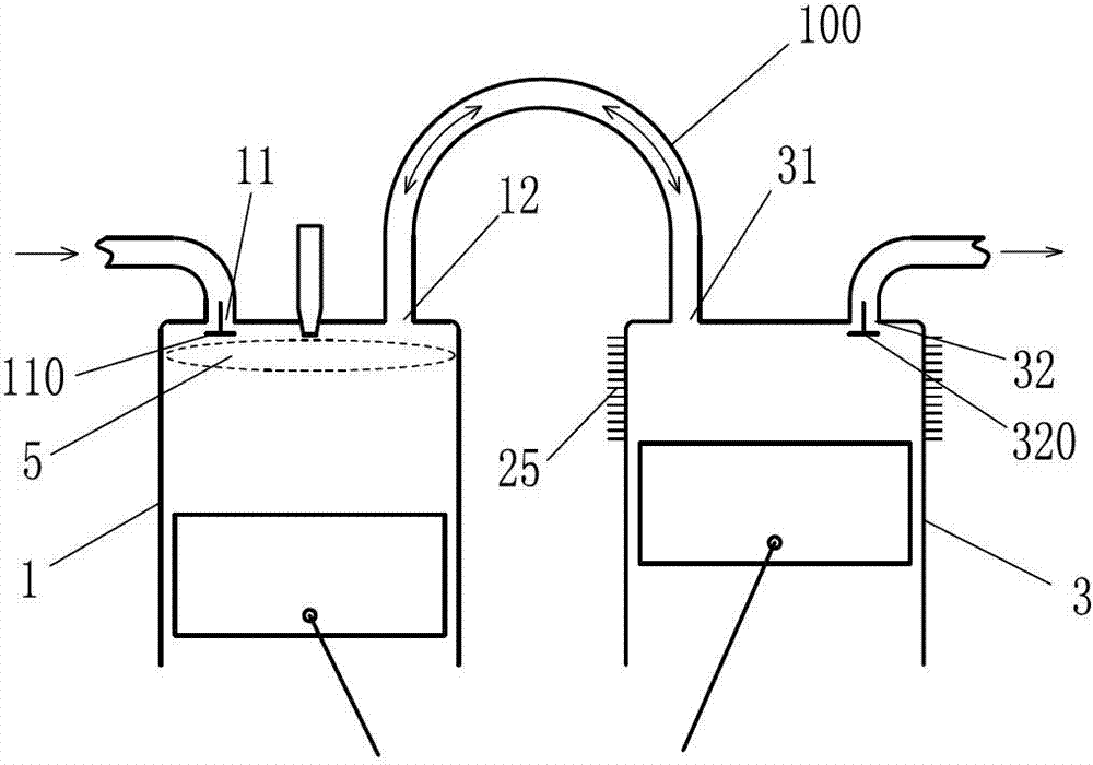
[0098] Such as figure 2 The three types of door hot gas engines shown are based on Embodiment 1: a cooler 25 is provided on the cylinder of the auxiliary cylinder-piston mechanism 3 .

[0099]The intake valve 110 on the cylinder of the cylinder-piston mechanism 1 and the exhaust valve 320 on the cylinder of the auxiliary cylinder-piston mechanism 3 are all controlled by the control mechanism of the engine of the present invention, so that the cylinder-piston mechanism 1. Work according to the eight-stroke cycle mode of suction stroke-compression stroke-combustion expansion power stroke-air supply stroke-backfill stroke-air supply stroke-backfill stroke-air supply stroke.

[0100] Optionally, the cooler 25 may also be provided on the reciprocating communication channel 100 .

Embodiment 3

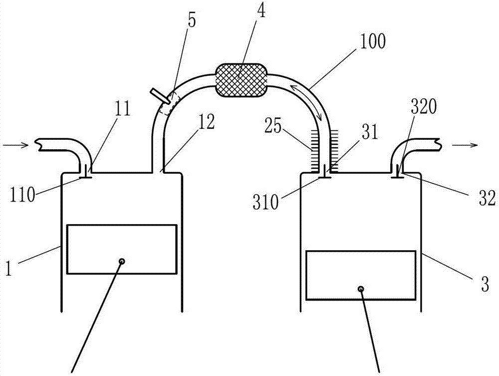
[0102] Such as image 3 The difference between the three-type door hot gas engine shown in Embodiment 2 is that a corresponding auxiliary reciprocating flow control door 310 is provided at the auxiliary reciprocating flow port 31, and a regenerator 4 is provided on the reciprocating communication channel 100. . The cooler 25 is instead arranged on the reciprocating communication channel 100 between the regenerator 4 and the auxiliary air inlet 31; the combustion chamber 5 is arranged between the regenerator 4 and the In the reciprocating communication channel 100 between the reciprocating flow ports 12 .

[0103] Open the intake valve 110, the cylinder-piston mechanism 1 sucks air through the intake port 11, close the intake valve 110 and the auxiliary reciprocating flow control door 310, and the work in the cylinder-piston mechanism 1 The working fluid is compressed in the cylinder-piston mechanism 1 and the reciprocating communication passage 100, and the compressed workin...


PUM


Abstract

The invention discloses a three-valve hot-air engine which includes a cylinder piston mechanism. An air cylinder of the cylinder piston mechanism is provided with an air inlet and a reciprocating flow mouth. A corresponding inlet valve is arranged at the position of the air inlet. The three-valve hot-air engine further includes a subsidiary cylinder piston mechanism. The cylinder of the subsidiary cylinder piston mechanism is provided with a subsidiary reciprocating flow mouth and an exhaust air outlet, and a corresponding exhaust-valve is arranged at the position of the exhaust air outlet. The reciprocating flow mouth is communicated with the subsidiary reciprocating flow mouth through a reciprocating communicating channel. A combustion case is arranged inside the cylinder of the cylinder piston mechanism and / or inside the reciprocating communicating channel and / or inside a channel communicated with the air inlet. The three-valve hot-air engine achieves further use of the heat in working medium after working again for the combustion explosion so as to enable the thermal efficiency of the engine to be improved, and has the advantages of being beneficial for saving energy, simple in structure, strong in practicability, and broad in application prospect.

Description

technical field [0001] The invention relates to the field of thermal power, in particular to a heat engine. Background technique [0002] Traditional internal combustion engines generally discharge high-temperature exhaust gas directly, resulting in serious heat loss. However, the gas working medium in the traditional heat engine needs heat to heat, and the conventional heating method is external combustion, and the fuel usage efficiency is low. An engine that further utilizes the waste heat from the engine exhaust. Contents of the invention [0003] In order to solve the above problems, the technical scheme proposed by the present invention is as follows: [0004] Scheme 1: a three-type door hot gas engine, including a cylinder-piston mechanism, the cylinder of the cylinder-piston mechanism is provided with an air intake port and a reciprocating flow port, and the air intake port is provided with a corresponding intake valve. The three-type door hot gas engine also inc...

Claims


Application Information

Patent Timeline
Patent Type & Authority Applications(China)
IPC IPC(8): F02G1/044F02G1/053F02G1/045
Inventor 靳北彪
Owner ZEROQ SCI & TECH
Why Eureka
Try Eureka