Rotary compressor and control method thereof

A technology of rotary compressor and compression mechanism, which is applied in the control of rotary machinery and in the field of rotary compressors, and can solve the problems that the lubricating oil cannot be recycled in time, the compressor lacks lubricating oil, and the compressor lacks lubricating oil. Achieve the effect of simple structure, simple structure and low cost

Active Publication Date: 2016-03-30
EMERSON CLIMATE TECH (SUZHOU) CO LTD
View PDF13 Cites 0 Cited by
  • Summary
  • Abstract
  • Description
  • Claims
  • Application Information

AI Technical Summary

Problems solved by technology

In this dual or multi-compressor system, one or more of the compressors can be selectively started and the others can be shut down, so the lubricating oil will move in these compressors and may cause The lubricating oil is not balanced, and even some compressors lack lubricating oil
[0004] In addition, whether it is in a compressor system composed of a single compressor or in a multi-compressor system composed of multiple compressors, there may be a lack of lubricating oil due to oil leakage in the compressor system or the compressor.
[0005] In addition, in a large-scale refrigeration system, due to the long pipeline length and many components, the lubricating oil may not be circulated back to the compressor in time, causing the compressor to lack lubricating oil.

Method used


Image

  • Rotary compressor and control method thereof
  • Rotary compressor and control method thereof
  • Rotary compressor and control method thereof

Examples


Embodiment Construction

[0063] The following description of preferred embodiments is exemplary only and in no way restricts the invention and its application or usage.

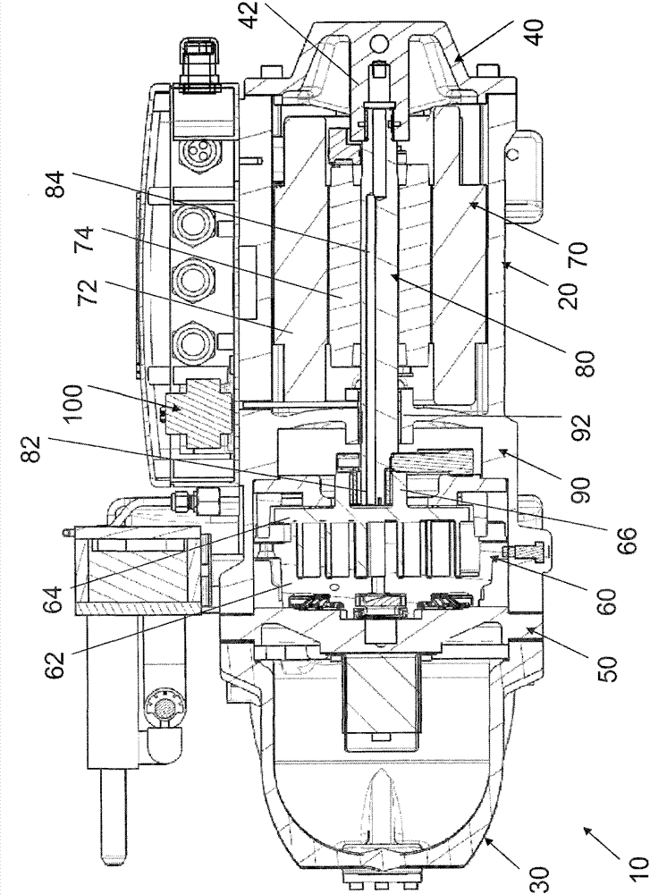
[0064] The following will refer to figure 1 A basic configuration of a rotary compressor according to an embodiment of the present invention is described. figure 1 is a schematic sectional view of a rotary compressor according to an embodiment of the present invention. figure 1 The rotary compressor shown is a scroll compressor, however, those skilled in the art should understand that the embodiments of the present invention are not limited to the scroll compressor shown in the figure, but the present invention can also be applied to other types of compressors. compressors including a rotating shaft, such as screw compressors, rotary compressors, etc., and any type of rotating machinery including a rotating shaft. In addition, the present invention is applicable not only to horizontal compressors whose rotary shafts are oriented ho...


PUM


Abstract

The invention relates to a rotary machine. The rotary machine comprises a shell (20), a main bearing base (90) fixedly arranged in the shell, a revolving shaft (80) and a pressure sensor (120), wherein the main bearing base is internally provided with a main bearing (92), the main bearing base can rotatably support the revolving shaft (80) through the main bearing, the revolving shaft is internally provided with a through hole (84) which axially extends along the revolving shaft, and the through hole (84) forms one part of a lubricating oil loop; and the pressure sensor (120) is communicated with a fluid in the through hole (84) through a lubricating oil detecting channel (110), and the pressure sensor outputs a cut-off signal when the pressure formed by lubricating oil from the lubricating oil detecting channel is less than a predetermined value. The invention also relates to a control method of the rotary machine, and when the pressure sensor detects that the fluid pressure generated by the lubricating oil flowing in the through hole is lower than the predetermined value, the operation of the rotary machine is stopped. According to the invention, the amount of the lubricating oil in the rotary machine can be directly and reliably detected.

Description

technical field [0001] The present invention relates to a rotary machine, especially a rotary compressor, and also relates to a control method of the rotary machine. Background technique [0002] A rotary compressor is one of rotary machines and generally includes a housing, a compression mechanism accommodated in the housing, a driving mechanism for driving the compression mechanism, a rotary shaft driven by the driving mechanism, and the like. Typically, axially extending oil holes are provided in the rotating shaft to supply lubricating oil to various moving parts of the compressor. In order to ensure the normal operation of the compressor, there must be enough lubricating oil in the oil hole of the rotating shaft to ensure that various moving parts are fully lubricated. When the amount of lubricating oil flowing in the oil hole is lower than a predetermined value, the compressor should be stopped to protect the compressor. [0003] At present, dual or even multi-compre...

Claims


Application Information

Patent Timeline
Patent Type & Authority Patents(China)
IPC IPC(8): F04C28/28
Inventor 方柳霞刘轩詹宏宏
Owner EMERSON CLIMATE TECH (SUZHOU) CO LTD
Why Eureka
Try Eureka