
Energy-saving high-temperature industrial equipment cooling device

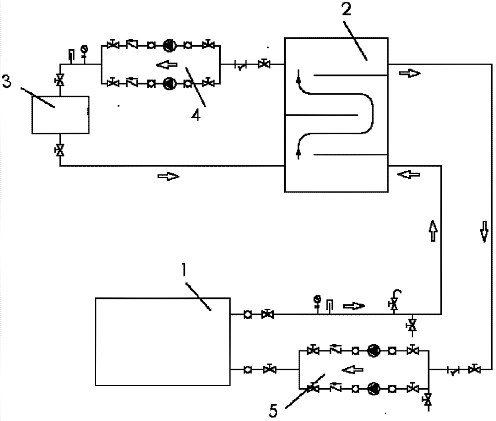
A high-temperature industry and cooling device technology, applied in household refrigeration devices, lighting and heating equipment, household appliances, etc., can solve problems such as shortened life of chillers and water pumps, energy consumption, and occupation of factory space

Inactive Publication Date: 2013-05-08
SHANGHAI HANYE REFRIGERATION MACHINERY
View PDF5 Cites 2 Cited by
  • Summary
  • Abstract
  • Description
  • Claims
  • Application Information

AI Technical Summary

Problems solved by technology

In addition, there is no three-way proportional regulating valve between the water inlet and outlet of the industrial chiller, so it is difficult to maintain the temperature of the water inlet of high-temperature industrial equipment at a given value
The disadvantage of this high-temperature cooling scheme is that the temperature entering the mixing water tank from high-temperature industrial equipment is very high, so it is necessary to choose an industrial chiller with a large cooling capacity. Only in this way can the mixed water meet the needs of high-temperature industrial equipment, and the corresponding large refrigeration A large number of industrial chillers also means large power consumption, and occupy a relatively large workshop space, which is difficult to meet the requirements of energy saving. At the same time, there is no three-way proportional regulating valve between the water inlet and outlet of the industrial chiller, which will cause frequent start and stop. Chillers, water pumps and other equipment, so the life of chillers and water pumps will be shortened, and more energy-consuming, and even affect the operation of high-temperature industrial equipment

Method used


Image

  • Energy-saving high-temperature industrial equipment cooling device
  • Energy-saving high-temperature industrial equipment cooling device

Examples


Embodiment Construction

[0010] Below in conjunction with accompanying drawing and specific embodiment the present invention is described in further detail:

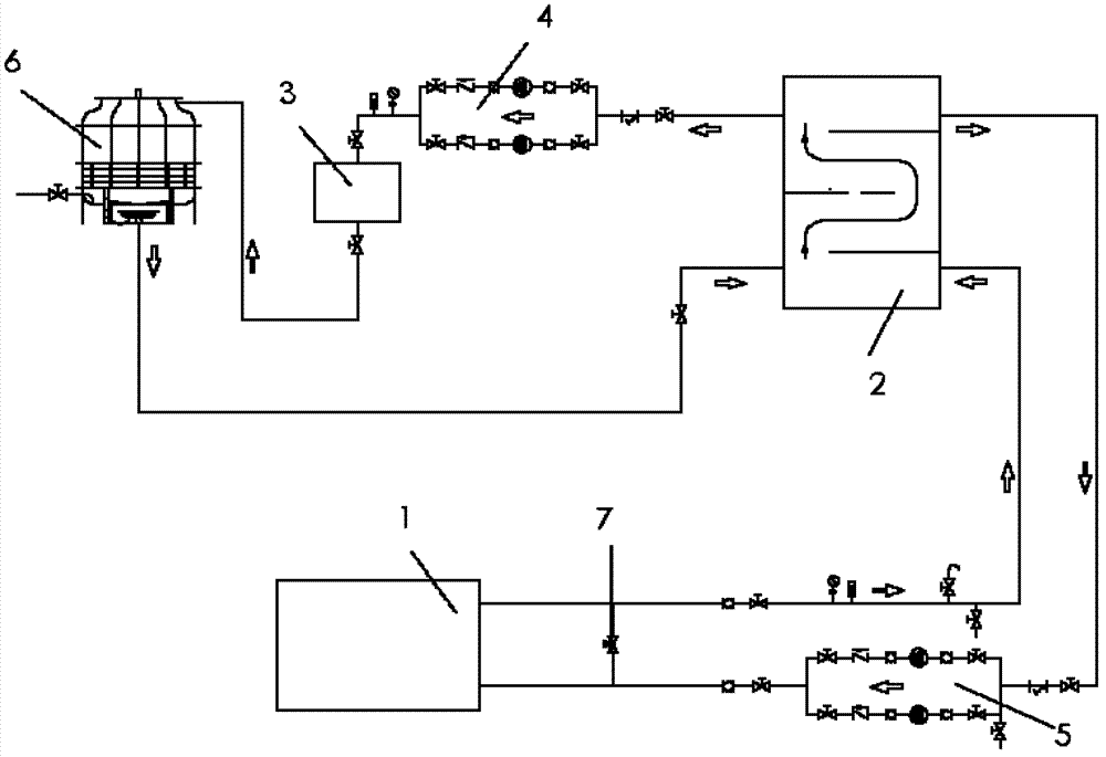
[0011] Depend on figure 2 It can be seen that the present invention includes: high-temperature industrial equipment 3; also includes: a cooling water tower 6; the outlet water of the high-temperature industrial equipment 3 is connected to the first water inlet of the mixing pool 2 through the cooling water tower 6; the first water inlet of the mixing pool 2 The water outlet is connected to the water inlet of the industrial chiller 1 through the refrigeration cycle pump 5; the water outlet of the industrial chiller 1 is connected to the second water inlet of the mixing pool 2; the second water inlet of the mixing pool 2 The water outlet is connected to the water inlet of the high-temperature industrial equipment 3 through the pressure circulation pump 4; a three-way proportional regulating valve 7 is also connected in parallel between the water ...


PUM


Abstract

The invention relates to an energy-saving high-temperature industrial equipment cooling device which comprises high-temperature industrial equipment and a cooling water tower. A water outlet of the high-temperature industrial equipment is connected with a first water inlet of a mixing water tank through the cooling water tower, a first water outlet of the mixing water tank is connected with a water inlet of an industrial water chiller through a refrigeration circulating pump, a water outlet of the industrial water chiller is connected with a second water inlet of the mixing water tank, a second water outlet of the mixing water tank is connected with a water inlet of the high-temperature industrial equipment through a pressure circulating pump, and a three-way proportioning valve is parallelly connected between the water inlet and the water outlet of the industrial water chiller. The energy-saving high-temperature industrial equipment cooling device has the advantages that owing to addition of the cooling water tower and the three-way proportioning valve, an industrial water chiller with high refrigerating capacity is omitted, and the service lives of the industrial water chiller, a water pump and even the high-temperature industrial equipment are prolonged.

Description

technical field [0001] The invention relates to a cooling device, in particular to a cooling device for high-temperature industrial equipment. Background technique [0002] The cooling solution for high-temperature industrial equipment consists of industrial chiller 1, mixing pool 2, high-temperature industrial equipment 3, three-way proportional regulating valve, water pump and other pipelines. The water output from high temperature industrial equipment 3 enters the mixing pool 2 and is mixed with the water output from industrial chiller 1 to provide to high temperature industrial equipment. In the figure: pressure circulation pump 4 and refrigeration circulation pump 5. [0003] The traditional high-temperature cooling solution is that the effluent of high-temperature industrial equipment directly enters the mixing water tank and mixes with the effluent of industrial chillers to provide high-temperature industrial equipment. In addition, there is no three-way proportional...

Claims


Application Information

Patent Timeline
IPC IPC(8): F25D1/00
Inventor 卢大民
Owner SHANGHAI HANYE REFRIGERATION MACHINERY
Learn More