
A test method for laser cleaning threshold

A technology of laser cleaning and testing method, applied in the field of laser cleaning, to achieve the effect of reducing a large number of repetitive experiments, realizing automation, and saving experimental costs

Active Publication Date: 2014-10-29
JIANGSU UNIV
View PDF2 Cites 6 Cited by
  • Summary
  • Abstract
  • Description
  • Claims
  • Application Information

AI Technical Summary

Problems solved by technology

These detection devices can obtain the laser cleaning threshold of the material, but they can only rely on a large amount of experimental data to find the threshold. When cleaning different materials, a large number of repeated experiments are required.

Method used


Image

  • A test method for laser cleaning threshold
  • A test method for laser cleaning threshold

Examples


Embodiment

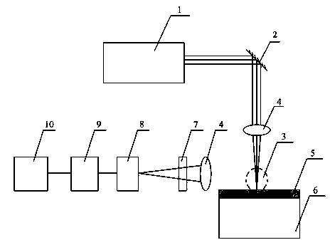
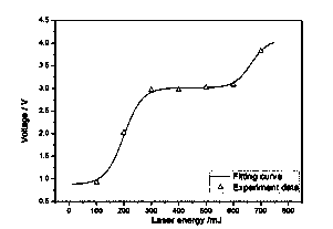
[0018] Using 1064nm Nd:YAG pulsed solid-state laser, the energy can be adjusted from 0 to 1000mJ, respectively measuring 100mJ, 200mJ, 300mJ, 400mJ, 500mJ, 600mJ, 700mJ laser energy value impacting the material surface, the detected laser plasma is converted into voltage After the signal is obtained, the peak voltage value is obtained, and after calculation, a=-0.01937, b=1.01746, c=298.31989, g=654.21055, d=0.0125, h=0.01447, p=0.67202. Through experimental verification, it is found that the laser cleaning threshold is 300mJ and the laser damage threshold is 654mJ. The laser cleaning threshold is basically the same as the calculated value c, and the laser damage threshold is basically the same as the calculated value g. by figure 2 As shown, the peak voltage values ​​obtained by the above selected 100mJ, 200mJ, 300mJ, 400mJ, 500mJ, 600mJ, 700mJ are consistent with the calculated fitting curve.


PUM


Abstract

The invention discloses a laser cleaning threshold value test method. The laser cleaning threshold value test method includes the following steps: setting initial laser energy value, detecting laser plasma signals generated by laser shock materials, transforming the laser plasma signals into voltage signals and obtaining peak voltage value, and substituting the laser energy value and the peak voltage value into the Bi Dose Resp function; changing the laser energy value, repeating the steps more than five times, obtaining different equation sets formed by the laser energy value and the peak voltage, and calculating laser cleaning threshold value and laser-damaged threshold value. The laser cleaning threshold value test method achieves automatic test of the laser cleaning threshold value.

Description

Technical field [0001] The invention belongs to the field of laser cleaning, and in particular relates to a method for testing laser cleaning threshold. Background technique [0002] In the laser cleaning process, if the laser energy is too high, it will damage the substrate, but if the energy is too low, the surface cannot be cleaned. Therefore, there are laser cleaning thresholds and laser damage thresholds. Before laser cleaning, the first step is to determine the laser energy, the energy selection must be greater than the cleaning threshold and less than the damage threshold. At present, there are two ways to obtain the laser cleaning threshold. One is the acoustic detection method, which uses pulsed laser to radiate the surface of the substrate to generate strong vibration shock waves in a short period of time. The surface of the substrate generates sound waves, which are collected by using acoustic instruments such as microphones. The cleaning threshold is judged by the in...

Claims


Application Information

Patent Timeline
Patent Type & Authority Patents(China)
IPC IPC(8): G01J1/42B08B7/00
Inventor 佟艳群张永康姚红兵张署光张罗王浩
Owner JIANGSU UNIV
Learn More