Method for estimating residual magnetism of transformer core based on slope of local hysteresis loop

A transformer core and hysteresis loop technology, applied in hysteresis curve measurement, magnetic performance measurement, etc., can solve the problems of low recognition accuracy of residual magnetism, difficult mathematical model description, and poor applicability of engineering transformers. Achieve the effect of simple measurement and calculation method of residual magnetism, clear physical meaning and low test power

Active Publication Date: 2018-02-02
STATE GRID JIANGSU ELECTRIC POWER CO ELECTRIC POWER RES INST +3
View PDF7 Cites 28 Cited by
  • Summary
  • Abstract
  • Description
  • Claims
  • Application Information

AI Technical Summary

Problems solved by technology

[0004] 1) Estimating the remanence by identifying the remanence at the saturation moment and establishing the relationship between the transformer opening angle and the core remanence, but this method requires a large number of airdrop experiments on the transformer, and the accurate identification of the saturation moment depends on the inductance Therefore, the accuracy of remanence identification is not high;
[0005] 2) The continuous function, arctangent function and preisach model are used to describe the magnetic characteristics of the iron core respectively. By recording the current amplitude and phase at the opening moment, the residual magnetism is estimated by using the local hysteresis loop. The magnetic flux change is a complex transient process affected by factors such as transformer equivalent capacitance, which is difficult to describe through a simple mathematical model;
[0008] Most of the above remanence estimation methods need to record the current at the moment of opening, and have certain limitations on the application of three-phase three-column transformers or three-phase five-column transformers. The application of practical engineering transformers is not strong

Method used


Image

  • Method for estimating residual magnetism of transformer core based on slope of local hysteresis loop
  • Method for estimating residual magnetism of transformer core based on slope of local hysteresis loop
  • Method for estimating residual magnetism of transformer core based on slope of local hysteresis loop

Examples


Embodiment

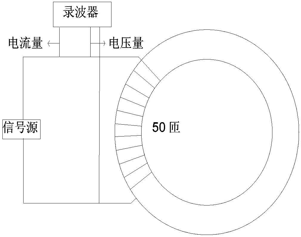
[0057] Step 1, measure the saturation hysteresis loop of the transformer core material.

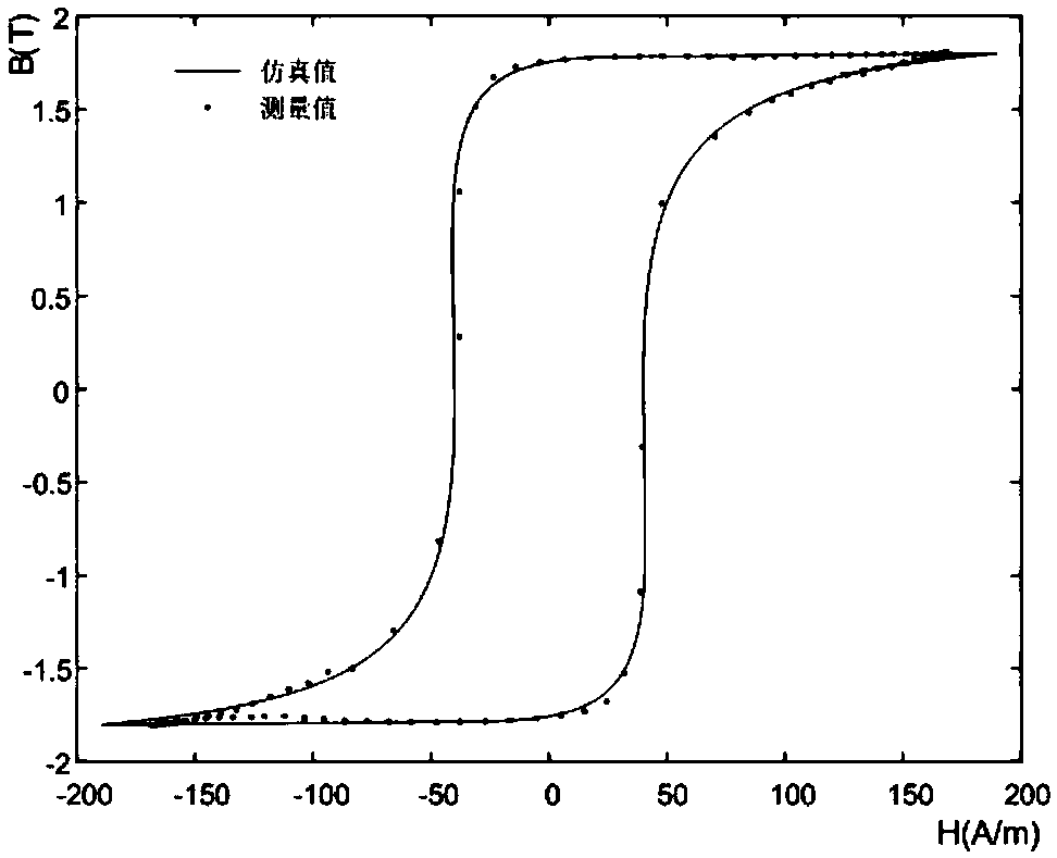
[0058] Such as figure 1 As shown in , a low-frequency AC current is applied to the coil on one side of the transformer (here in order to measure the saturation hysteresis loop and obtain the corresponding JA model parameters, so a low-frequency AC current should be applied.), the frequency is generally taken as 5HZ, and the amplitude is based on The magnetic hysteresis of the iron core material is specific, and the voltage and current data at both ends of the coil are recorded, and the voltage-current relationship is converted into the relationship between the magnetic induction intensity B and the magnetic field intensity H,

[0059] Note: In this step, low-frequency AC current is applied, and multiple cycles need to be applied until the voltage and current values ​​tend to be stable (the stability here is not not changing, but changing steadily along the saturation hysteresis loop with ...


PUM


Abstract

The invention relates to a method for estimating the residual magnetism of a transformer core based on the slope of a local hysteresis loop, which comprises the following steps: S1, measuring the saturation hysteresis loop of a transformer core material; S2, using a JA model to simulate the hysteresis characteristic of the transformer coil; S3, getting the relation between the residual magnetism and the slope of a local hysteresis loop near a residual magnetism point based on the JA model, and fitting the relation to get a corresponding formula relation; and S4, powering on and testing a transformer coil under test, getting the positive and negative slope near the residual magnetism point through electromagnetic relation conversion, and calculating the residual magnetism value according tothe formula obtained in the previous step. The method of the invention is simple. There is only the need to apply small positive and negative excitation and record the voltage and current in the residual magnetism calculation experiment. No complicated online experiment is needed. The test power is low, and the experimental cost is low.

Description

technical field [0001] The invention specifically relates to a method for estimating residual magnetism of transformer iron cores in various forms such as single-phase, three-phase and three-column types. Background technique [0002] When the power transformer is powered on with no load or light load, the existence of residual magnetism in the iron core will make the iron core of the transformer saturate quickly for half a cycle, and generate an excitation inrush current whose amplitude can reach 6 to 8 times the normal steady-state current. The large inrush current contains a large number of harmonics, which affects the power quality, causes relay protection malfunctions, and affects the safe operation of the power grid. Synchronous closing technology and phase-selection closing technology are effective measures to suppress the excitation inrush current, and the effective measurement and calculation of the magnitude and direction of residual magnetism is the premise of pha...

Claims


Application Information

Patent Timeline
Patent Type & Authority Applications(China)
IPC IPC(8): G01R33/12G01R33/14
Inventor 李建生陶风波周志成魏旭吴益明杨小平蔚超吴鹏陆云才廖才波
Owner STATE GRID JIANGSU ELECTRIC POWER CO ELECTRIC POWER RES INST
Why Eureka
Try Eureka