Sub-ultrasonic high-frequency fatigue testing machine

A fatigue testing machine, sub-ultrasonic technology, applied in the direction of applying repeated force/pulsation force to test material strength, etc., can solve problems such as time and economic cost constraints, material fatigue, fatigue size effect, etc., to shorten the test cycle and reduce Frequency effect and size effect, simple structure effect

Active Publication Date: 2013-05-08
天津益普科技发展有限公司
View PDF6 Cites 21 Cited by
  • Summary
  • Abstract
  • Description
  • Claims
  • Application Information

AI Technical Summary

Problems solved by technology

Such a large time and economic cost limit the current high-cycle and ultra-high-cycle fatigue tests and research
The frequency of the existing ultrasonic fatigue testing machine is about 20kHz, which will bring about the frequency effect

Method used


Image

  • Sub-ultrasonic high-frequency fatigue testing machine
  • Sub-ultrasonic high-frequency fatigue testing machine
  • Sub-ultrasonic high-frequency fatigue testing machine

Examples


Embodiment Construction

[0027] The technical solution of the present invention will be further described in detail below in conjunction with specific embodiments and accompanying drawings.

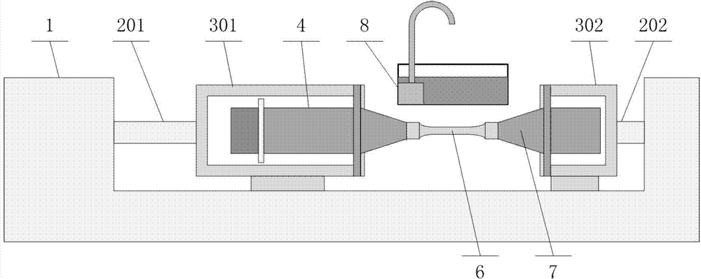
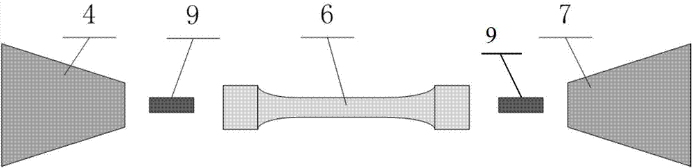
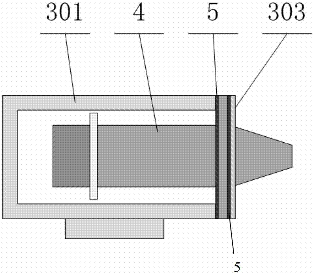
[0028] Reference attached figure 1 Shown in -7, the high-frequency fatigue testing machine of the present invention is by a transducer that converts electrical energy into mechanical energy as a driving force source, and relies on its inverse piezoelectric effect or magnetostrictive effect to convert alternating voltage into alternating voltage. deformation, and then provide vibration excitation to the system. The specific structure is as follows:

[0029] Test body 1, static load output shaft 201, fixed shaft 202, main jig 301, slave jig 302: one end of the test body 1 is fixedly provided with the fixed shaft 202 and the slave jig 302, and the other end of the test body 1 is provided with a The telescopic static load output shaft 201, the slide rail structure is adopted between the main jig 301 and the test bo...


PUM


Abstract

The invention discloses a sub-ultrasonic high-frequency fatigue testing machine. An energy converter used as a driving force source, the energy converter, a tested sample and a driven amplitude transformer form a resonance system, and a prearranged static loading mechanism provides static load for a test piece. The energy converter can be a full-wavelength energy converter or a half-wavelength energy converter. The energy converter converts an electric signal into mechanical vibration under the driving of an external alternating voltage, so the whole system is in a resonance state, and the tested sample has resonance vibration and a stress, thereby the fatigue detection can be realized. The energy converter can be a piezoelectric energy converter or a giant magnetostrictive energy converter. The sub-ultrasonic high-frequency fatigue testing machine allows the sub-ultrasonic high-frequency fatigue tests of the test piece under different stress ratios to be carried out according to the system prearrangement state; compared with traditional high-frequency fatigue testing machines, the sub-ultrasonic high-frequency fatigue testing machine has the advantages of simple structure, small volume, test period shortening, high efficiency and energy saving; and compared with present ultrasonic fatigue testing machines, the sub-ultrasonic high-frequency fatigue testing machine has the advantage of reduction of the frequency effect and the dimension effect to the material fatigue performances.

Description

technical field [0001] The invention belongs to the field of fatigue detection and testing, and more specifically relates to a fatigue testing device at a sub-ultrasonic frequency (5kHz-15kHz). Background technique [0002] High-frequency fatigue testing machine is widely used in testing the fatigue properties of metal and non-metallic components such as tension and compression, torsion, bending, pitting corrosion, etc. , electronics, aviation, aerospace, metallurgy and other fields have a wide range of applications. Existing high-frequency fatigue testing machines are all driven by electromagnetic drive or electro-hydraulic servo drive, and the general working frequency is not more than 500Hz. However, the high cycle fatigue cycle of the material is between 10 5 ~10 7 Between, the cycle of ultra-high cycle fatigue is as high as 10 8 above. Such a large time and economic cost limit the current high-cycle and ultra-high-cycle fatigue tests and research. The frequency of...

Claims


Application Information

Patent Timeline
IPC IPC(8): G01N3/32G01N3/38
Inventor 王东坡吴良辰柳阳张涛黄超王颖
Owner 天津益普科技发展有限公司
Why Eureka
Try Eureka