Method and device for manufacturing fiber bragg grating (FBG) with random reflection wavelength overlength

A fiber grating and optical fiber technology, which is applied in the fields of optoelectronic technology and optical fiber communication, can solve the problems of time-consuming grating production, high requirements for precise optical fiber movement control, and difficulty in grating production, and achieves the effect of variable chirp function.

Active Publication Date: 2013-05-08
TSINGHUA UNIV
View PDF3 Cites 7 Cited by
  • Summary
  • Abstract
  • Description
  • Claims
  • Application Information

AI Technical Summary

Problems solved by technology

Although this method is highly flexible and can form gratings, chirped gratings, phase-shifting gratings, etc. for each reflection wavelength by precisely controlling the distance that the optical fiber moves, there are many practical limitations.
First, the production of point-by-point gratings is time-consuming and can only be used to make short gratings; second, the precise movement control of optical fibers is very demanding, and the cumulative effect of movement errors makes it difficult to make longer gratings; 3. Since it is technically difficult to achieve focusing the light spot into a light spot within the grating period, it is difficult to make a fiber grating with a reflection wavelength of less than 1 micron

Method used


Image

  • Method and device for manufacturing fiber bragg grating (FBG) with random reflection wavelength overlength
  • Method and device for manufacturing fiber bragg grating (FBG) with random reflection wavelength overlength
  • Method and device for manufacturing fiber bragg grating (FBG) with random reflection wavelength overlength

Examples


Embodiment 1

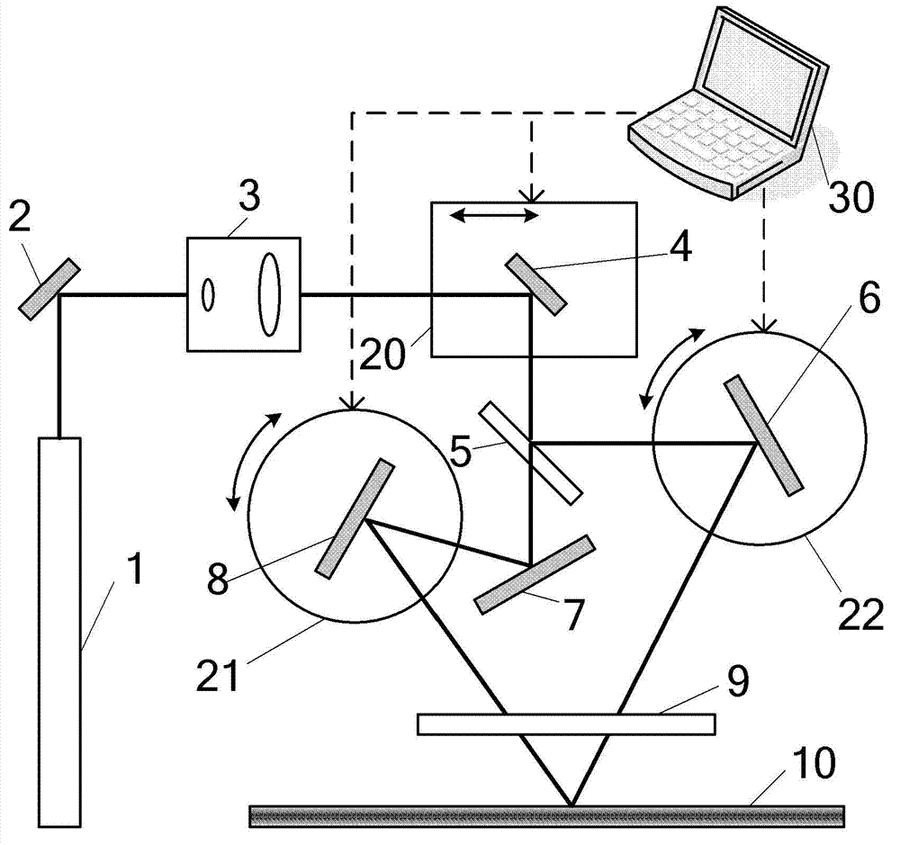
[0046] figure 1 It is a structural schematic diagram of the fiber grating fabricating device in Embodiment 1 of the present invention. Such as figure 1 As shown, the holographic interference laser generating device of the device consists of a laser 1, a first total reflection mirror 2, a beam expander system 3, a second total reflection mirror 4, a beam splitter 5, a third total reflection mirror 6, and a fourth total reflection mirror 7. The fifth total reflection mirror 8 and the cylindrical lens 9 are composed. The holographic interference laser translation device is realized by an electronically controlled translation stage 20, which is used to carry the second total reflection mirror 4. The rotating device includes a first electrically controlled rotating table 21 and a second electrically controlled rotating table 22, which are used to mount the third total reflection mirror 6 and the fifth total reflection mirror 8 respectively. In addition, the scanning control devi...

Embodiment 2

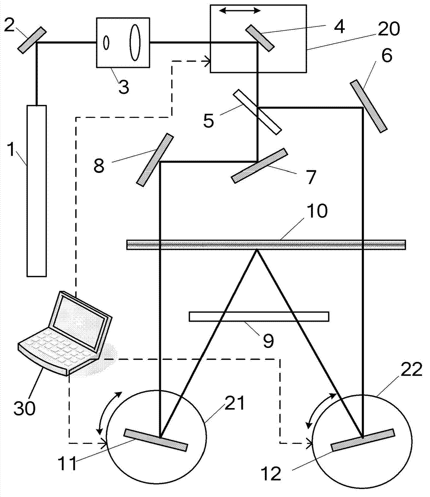
[0060] figure 2 It is a structural schematic diagram of the fiber grating fabricating device according to the second embodiment of the present invention. The structure of this embodiment is basically the same as that of Embodiment 1, the difference is that, except for the optical element in Embodiment 1, the holographic interference laser generating device of this embodiment also includes two total reflection mirrors, namely the sixth total reflection mirror 11 And the seventh total reflection mirror 12. The sixth total reflection mirror 11 and the seventh total reflection mirror 12 are arranged on the other side of the optical fiber, that is, the side opposite to the beam splitter 5 and the third to fifth total reflection mirrors 6 , 7 , 8 . Moreover, the laser light reflected by the third and fifth total reflection mirrors 6 and 8 is respectively incident on the sixth and seventh total reflection mirrors 11 and 12, and then reflected by the sixth and seventh total reflecti...


PUM


Abstract

The invention discloses a method and a device for manufacturing fiber bragg gratings (FBG) with a random reflection wavelength overlength. The method includes: using two bundles of holographic interference lasers to be incident into light fibers at a certain included angle from one side of the light fibers to generate holographic interference; and meanwhile, through an electronic control translation platform controlled by a computer, enabling the two bundles of holographic interference lasers to translate along the length direction of the light fibers, and through a computer-controlled electronic control rotating platform or a computer-controlled electronic control plane mirror frame, adjusting the included angle of the two bundles of holographic interference lasers. Writing of the FBG with random reflection wavelength overlength can be achieved, and the FBGs include narrow reflector tape gratings, chirp gratings, apodization gratings and the like.

Description

technical field [0001] The invention belongs to the field of optoelectronic technology and optical fiber communication technology, and specifically relates to a method and a device for manufacturing an optical fiber grating, in particular to a general method and device for manufacturing an ultra-long optical fiber grating with any reflection wavelength. Background technique [0002] As early as 1978, K.O.Hill et al. used the standing wave method to write fiber Bragg gratings successfully in Ge-doped silica fiber for the first time, which aroused great interest of researchers in the fabrication and application of fiber gratings. So far, fiber gratings have been widely used in the fields of optical fiber sensing, optical fiber communication and fiber laser due to their small size, light weight, high sensitivity, anti-electromagnetic interference and many other advantages. The grating obtained by the standing wave method can only work near the laser wavelength for making the gr...

Claims


Application Information

Patent Timeline
Patent Type & Authority Applications(China)
IPC IPC(8): G02B6/02
CPCG03H1/0005G03H1/0248G02B6/02085G02B6/02133G03H1/0236G03H2001/0439G03H2001/0482G03H2222/15G03H2270/20
Inventor 李宇航徐忠杨王力军
Owner TSINGHUA UNIV
Why Eureka
Try Eureka