Power management circuit

A power management and circuit technology, applied in the direction of program control, instruments, valve details, etc., can solve the problem of increased power consumption of the whole machine of the intelligent valve positioner, and achieve the effect of saving the power consumption of the whole machine

Active Publication Date: 2013-05-08
CHONGQING CHUANYI AUTOMATION
View PDF4 Cites 1 Cited by
  • Summary
  • Abstract
  • Description
  • Claims
  • Application Information

AI Technical Summary

Problems solved by technology

The pressure sensor can only work when it is powered on, and generally adding a pressure sensor needs to increase the power consumption by 0.6mA or more, so that when it is necessary

Method used


Image

  • Power management circuit

Examples


Example Embodiment

[0023] Example one

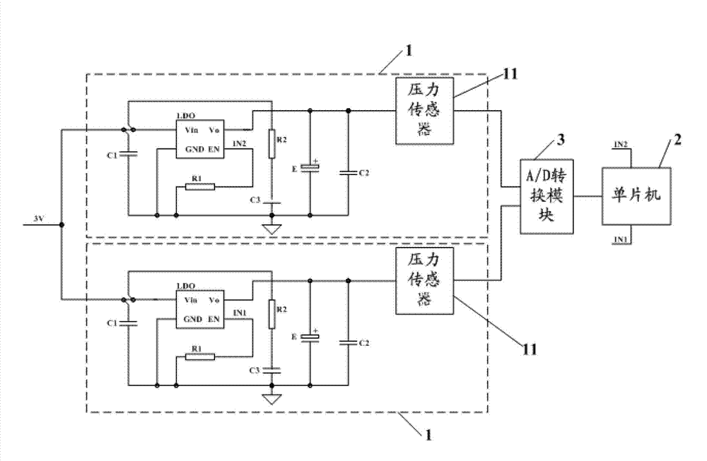
[0024] figure 1 A power management circuit diagram provided in the first embodiment of this application.

[0025] Such as figure 1 As shown, the power management circuit includes: two logic circuits 1 and a single-chip microcomputer 2, wherein the two logic circuits 1 are connected in parallel, and each logic circuit 1 includes a regulator LDO and a peripheral circuit to ensure the normal operation of the regulator LDO And pressure sensor 11.

[0026] Two IO interfaces are provided on the single-chip microcomputer 2. In the embodiment of the present application, the two IO interfaces on the single-chip microcomputer 2 are represented by IN1 and IN2, respectively. The main function of the two IO interfaces on the single-chip microcomputer is to send high and low level signals in rounds. In the embodiment of the present application, the time interval for the two IO interfaces on the single-chip microcomputer to send high and low signals in a round-robin manner ...


PUM


Abstract

The invention provides a power management circuit which comprises a single chip and a plurality of logic circuits. The single chip is provided with a plurality of input and output (IO) interfaces which are used for sending high and low level signals in a round-robin mode. Each logic circuit comprises a voltage stabilizer, a peripheral circuit which guarantees the voltage stabilizer to work normally and a pressure sensor. In the work process of the power management circuit, the single chip supplies the high and low level signals to an enable pin of the voltage stabilizer of each logic circuit in a round-robin mode, and therefore the voltage of an output end of the voltage stabilizer in each logic circuit is controlled. The voltage of the output end of the voltage stabilizer controls the pressure sensor to work, a round-robin mode is used in the power management circuit for supplying power to the pressure sensor, so that the pressure precision of detected gas is guaranteed, and meanwhile the power consumption of an intelligent valve positioner is saved.

Description

technical field [0001] The present application relates to the technical field of valve positioners, in particular to a power management circuit. Background technique [0002] Pneumatic regulating valve is one of the industrial process control instruments widely used in petroleum, chemical, electric power, pharmaceutical, metallurgical and other enterprises. The pneumatic regulating valve is usually formed by connecting the pneumatic actuator and the regulating valve after installation and debugging. By controlling the size of the pneumatic signal entering the pneumatic actuator, the opening of the regulating valve is controlled, thereby controlling the medium flow rate of the production device to reach a predetermined value. Among them, Controlling the size of the pneumatic signal entering the pneumatic actuator is mainly done through the intelligent valve positioner. Therefore, the intelligent valve positioner plays a decisive role in the control performance and field func...

Claims


Application Information

Patent Timeline
IPC IPC(8): G05B19/042F16K31/02
Inventor 马林刘小强蒋浩付健田博仁
Owner CHONGQING CHUANYI AUTOMATION
Why Eureka
Try Eureka