Radar ranging method and laser radar

A radar ranging and lidar technology, applied in the field of radar, can solve the problem of low light utilization rate, and achieve the effect of increasing the detection distance, reducing the power consumption of the whole machine, and reducing the signal light energy.

Pending Publication Date: 2021-02-05
BENEWAKE BEIJING TECH CO LTD
View PDF0 Cites 0 Cited by
  • Summary
  • Abstract
  • Description
  • Claims
  • Application Information

AI Technical Summary

Problems solved by technology

[0003] The embodiment of the present application is to propose a radar ranging method to solve the problem of low light utilization in the prior art. To achieve this purpose, the embodiment of the present application adopts the following technical solutions

Method used


Image

  • Radar ranging method and laser radar
  • Radar ranging method and laser radar
  • Radar ranging method and laser radar

Examples


Embodiment Construction

[0021] The technical solution of the present application will be further described below in conjunction with the accompanying drawings and through specific implementation methods.

[0022] It should be noted that, in the case of no conflict, the embodiments in the present application and the features in the embodiments can be combined with each other. The present application will be described in detail below with reference to the accompanying drawings and embodiments.

[0023] In order to enable those skilled in the art to better understand the solution of the present application, the technical solution in the embodiment of the application will be clearly and completely described below in conjunction with the accompanying drawings in the embodiment of the application. Obviously, the described embodiment is only It is an embodiment of a part of the application, but not all of the embodiments. Based on the embodiments in this application, all other embodiments obtained by perso...


PUM


Abstract

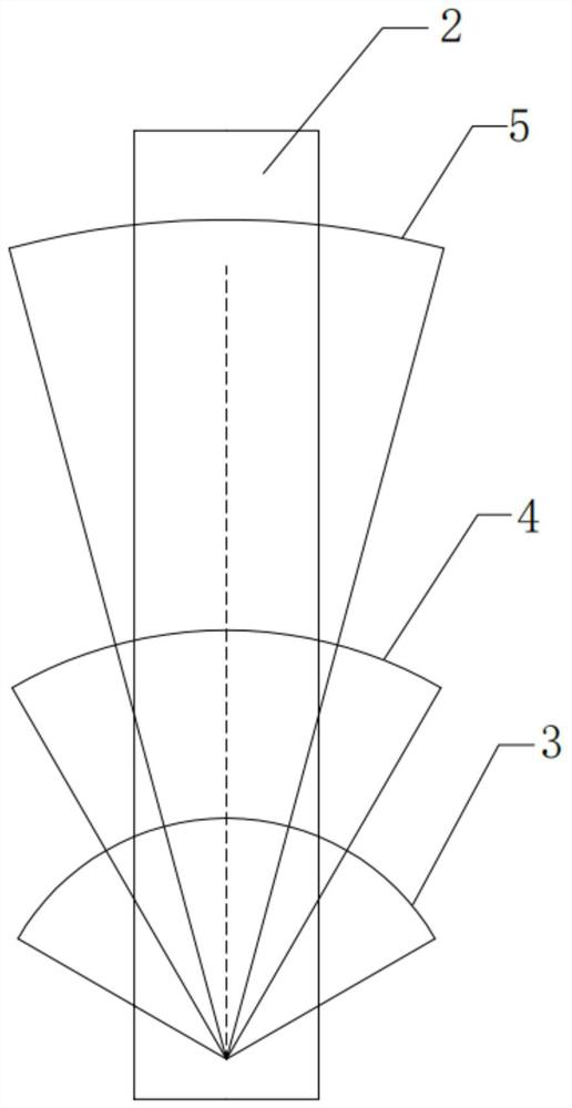
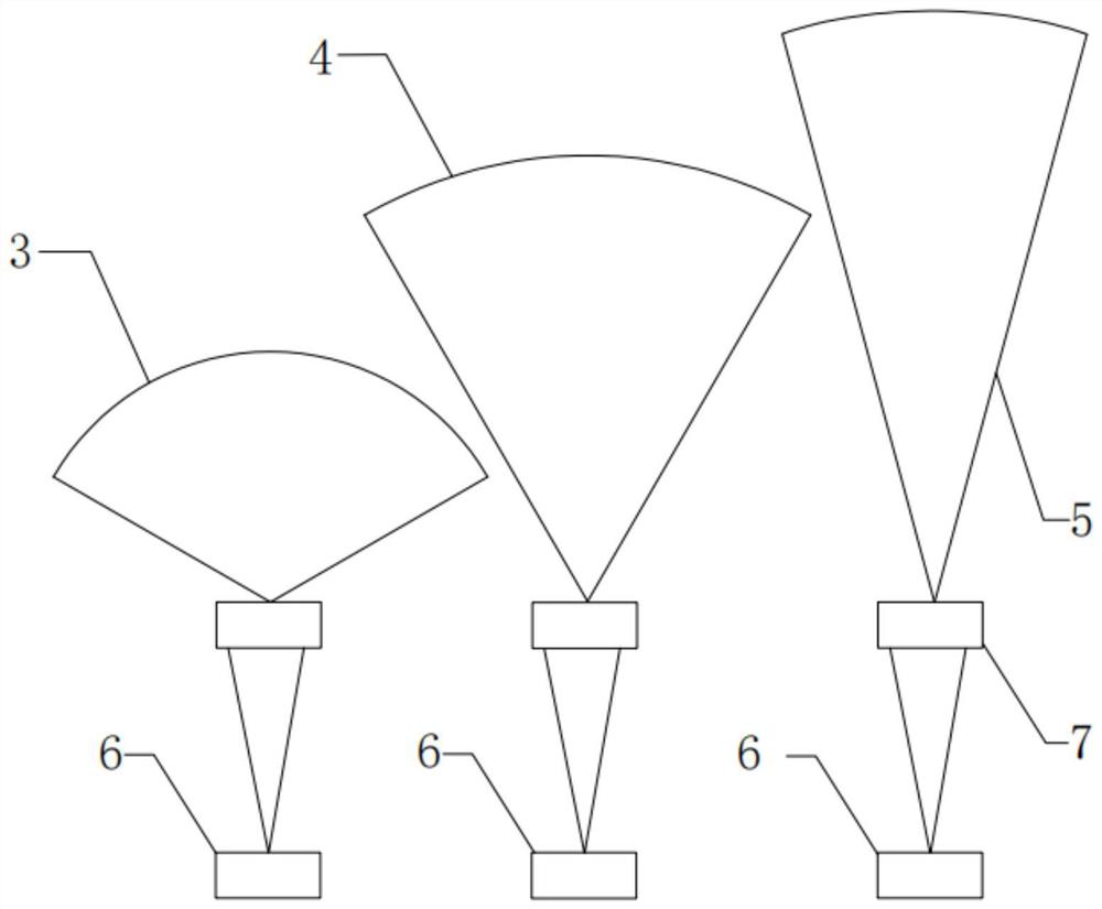
The invention relates to a radar signal light intensity distribution technology, in particular to a radar ranging method. A laser radar provided by the invention adopts signal light with different divergence angles, the first measurement distance uses the signal light with the first divergence angle, the second measurement distance uses the signal light with the second divergence angle, and the third measurement distance uses the signal light with the third divergence angle. Conversion of signal light of different divergence angles is achieved through switching of different light sources or processing of the same light source signal light through using an optical element. Because the larger the signal light detection distance is, the larger the divergence angle is, and the greater the required signal light energy is, the signal light with the smaller divergence angle is selected to detect the long distance, and the detection distance can be effectively increased under the condition that the existing signal light energy is not changed; or under the condition that the required detection distance is not changed, the signal light energy and the whole machine power consumption are effectively reduced, the operability is strong, and the applicability is strong.

Description

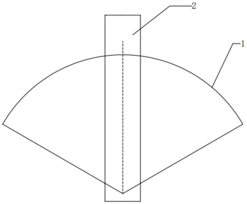
technical field [0001] The present application relates to a radar technology, in particular to a radar ranging method. Background technique [0002] At present, the known area array radar or depth camera mainly includes a signal light source, a beam shaping system, an optical receiving system, and a detector. The principle is that the signal light source emits signal light, which is processed by the beam shaping system and irradiates the target object. The light reflected by the target object is received by the optical receiving system, and then processed by the detector to obtain the result. Such as figure 1 In the laser radar ranging method shown, the signal light 1 emitted by the signal light source is a scattered light spot, covering a large field of view, and the light intensity distribution is generally a flat-top light intensity distribution (that is, on the light spot formed after beam shaping , the light intensity is roughly the same) or batwing light intensity di...

Claims


Application Information

Patent Timeline
Patent Type & Authority Applications(China)
IPC IPC(8): G01S17/08G01S7/481
CPCG01S7/481G01S17/08
Inventor 郑凯疏达李远
Owner BENEWAKE BEIJING TECH CO LTD
Why Eureka
Try Eureka