
Connectors and Electronics

A connector and electrical transmission technology, applied in the direction of connection, instruments, circuits, etc., can solve the problems of large cost and size burden, difficult to promote connectors, etc., to achieve the effect of maintaining backward compatibility and preventing obstruction

Inactive Publication Date: 2017-03-01
SONY CORP
View PDF7 Cites 2 Cited by
  • Summary
  • Abstract
  • Description
  • Claims
  • Application Information

AI Technical Summary

Problems solved by technology

In other words, since users bear a large burden in terms of cost and size, eventually such connectors themselves will not be used in devices, and thus such connectors are difficult to popularize

Method used


Image

  • Connectors and Electronics
  • Connectors and Electronics
  • Connectors and Electronics

Examples


Embodiment Construction

[0030] Embodiments of the present invention will be described in detail below with reference to the accompanying drawings. Note that description will be made in the following order.

[0031] 1. Example

[0032] Example: The electron transmission part is provided inside the electrical transmission housing (first housing), and the optical transmission part is provided outside the electrical transmission part.

[0033] 2. Modification

[0034] Example: Adoption of a protective cover for protecting the lens of the optical transmission part

[0035] 1. Example

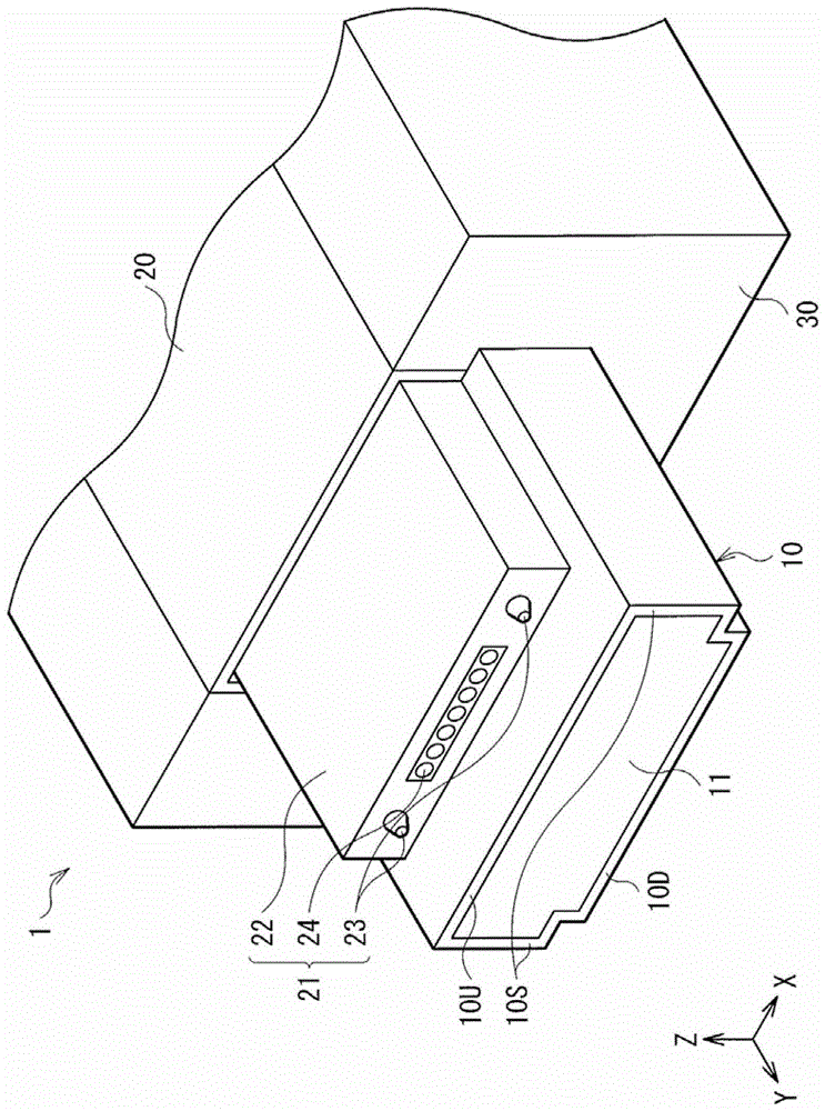
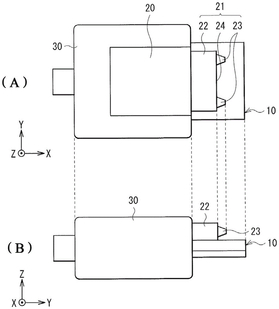
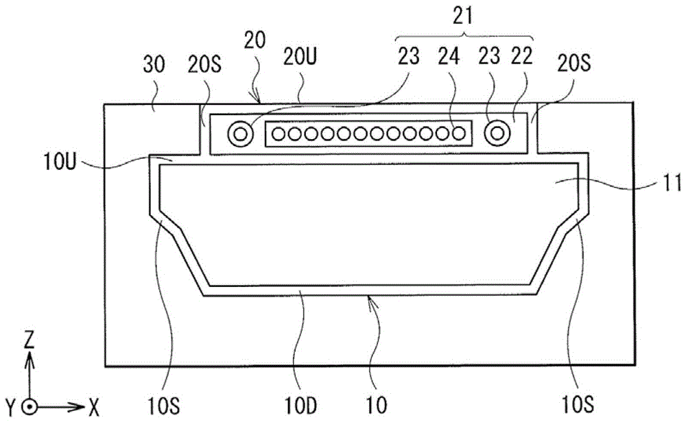
[0036] figure 1 The configuration of the main part of the connector (connector 1) of the embodiment of the present invention is shown. figure 2 (A) represents the structure of the upper surface (Z-axis direction) of the entire connector 1, figure 2 (B) represents the configuration of the side (X-axis direction) of the entire connector 1, and image 3 The structure of the front (Y-axis direction) of the whole connec...


PUM


Abstract

The present invention relates to connectors and electronic equipment. The connector includes: an electrical transmission part; an optical transmission part; and an isolation part disposed between the electrical transmission part and the optical transmission part. The electronic device has a connection of a type opposite to that of the connector. The connector and electronic device of the present invention have electrical transmission functions and optical transmission functions, and can be connected to existing electronic devices and connectors that only have electrical transmission functions, respectively, thus ensuring downward compatibility.

Description

[0001] Cross References to Related Applications [0002] This application contains subject matter related to the disclosure of Japanese Priority Patent Application JP2011-240830 filed in Japan Patent Office on Nov. 2, 2011, the entire contents of which are hereby incorporated by reference middle. technical field [0003] The present invention relates to connectors and electronic devices capable of electrical and optical transmission. Background technique [0004] Signal transmission between devices is performed by utilizing electrical signals such as USB (Universal Serial Bus (registered trademark)) and HDMI (High Definition Multimedia Interface (registered trademark)). However, in recent years, as the functions of MPUs (Micro Processing Units) have improved, the amount of data transmission has also increased significantly, so that electrical transmission has become inadequate in terms of capability and transmission rate. [0005] As a technology replacing or used for elec...

Claims


Application Information

Patent Timeline
Patent Type & Authority Patents(China)
IPC IPC(8): H01R27/00G02B6/32
CPCG02B6/32H01R27/02G02B6/3853G02B6/3885G02B6/3897G02B6/3817
Inventor 大鸟居英鸟羽一彰佐野和树铃木秀幸
Owner SONY CORP
Learn More