Message transmitting method and switching device based on bridge protocol data unit tunnel

A protocol data unit and switching equipment technology, applied in the field of communication, can solve the problem of wasting VLAN resources, etc., and achieve the effect of flexible LLDP neighbor relationship and reduced forwarding

Active Publication Date: 2013-05-08
NEW H3C TECH CO LTD
View PDF3 Cites 3 Cited by
  • Summary
  • Abstract
  • Description
  • Claims
  • Application Information

AI Technical Summary

Problems solved by technology

from figure 2 It can be seen in the figure that a link needs a VLAN ID to isolate ports to f

Method used


Image

  • Message transmitting method and switching device based on bridge protocol data unit tunnel
  • Message transmitting method and switching device based on bridge protocol data unit tunnel
  • Message transmitting method and switching device based on bridge protocol data unit tunnel

Examples


Example Embodiment

[0035] Embodiment one

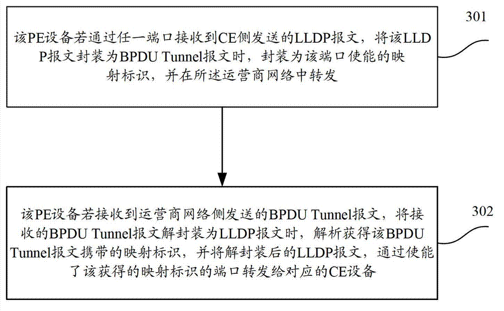
[0036] see image 3 , image 3 It is a schematic flowchart of a message forwarding method based on a bridge protocol data unit tunnel in Embodiment 1 of the present invention. The specific steps are:

[0037]Step 301, if the PE device receives the LLDP message sent by the CE side through any port, when the LLDP message is encapsulated into a BPDU Tunnel message, it is encapsulated as the mapping identifier enabled by the port, and the forwarded in the network.

[0038] The PE device enables one or more mapping identifiers for each port on the CE side. Therefore, when encapsulating the mapping identifiers enabled for this port, one or more mapping identifiers are encapsulated, even if several mapping identifiers are enabled, that is, in When encapsulating a message, encapsulate several.

[0039] When the PE device enables multiple mapping identities for a port, the number of enabled mapping identities does not exceed 255. When the number of mapping ...

Example Embodiment

[0043] Embodiment two

[0044] see Figure 4 , Figure 4 It is a schematic flow chart of the message forwarding method based on the bridge protocol data unit tunnel in the second embodiment of the present invention. The specific steps are:

[0045] Step 401, if the PE device receives the LLDP message sent by the CE side through any port, when encapsulating the LLDP message into a BPDU Tunnel message, add an extended type length value (TLV) to the BPDU Tunnel message, The extended TLV carries the mapping identifier enabled for the port, and is forwarded in the operator network.

[0046] see Figure 5 , Figure 5 It is a schematic diagram of the content in LLDP TLV format. Figure 5 The TLV type with a median value of 127 is used for extended definition, and sub tlv can be defined. For definition in 802.1AB see Image 6 , Image 6 It is a diagram of the content in the organization-specific TLV (Organizationally Specific TLV) format. Wherein, the sub type whose value is...

Example Embodiment

[0052] Embodiment three

[0053] Taking the establishment of many-to-one neighbor relationship as an example to illustrate the message forwarding method of the bridge protocol data unit tunnel. see Figure 8 , Figure 8 It is a schematic diagram of LLDP networking based on BPDU Tunnel in Embodiment 3 of the present invention.

[0054] Assume that link 1, link 2, and link 3 of CE device 1 need to establish a neighbor relationship with link 3 of CE device 2. When PE device 1 enables the LLDP function based on BPDU-Tunnel on its port PE1_Port1, enable mapping flag 1 at the same time, which can be realized by enabling the bpdu-tunnel dot1q lldp1 command line; PE device 1 enables BPDU-based LLDP on its port PE1_Port2 When the LLDP function of -Tunnel is enabled, the mapping flag 2 is enabled at the same time, which can be realized by enabling the bpdu-tunnel dot1q lldp2 command line; when PE device 1 enables the LLDP function based on BPDU-Tunnel on its port PE1_Port3, enable th...


PUM


Abstract

The invention discloses a message transmitting method based on a bridge protocol data unit tunnel. The message transmitting method based on the bridge protocol data unit tunnel comprises the following steps: a phase encoding (PE) device basing on link layer discovery protocol (LLDP) function of bridge protocol data unit tunnel (BPDU)-Tunnel on each port enables of a chip enable (CE) side, at the same time mapping identification for the port enables of the CE side, and transmitting carrying the mapping identification of the port enable when transmitting passing through LLDP message received by any port; when receiving message transmitted by operator networks, analyzing and obtaining the mapping identification carried by the BPDU-Tunnel message, and transmitting the message through the enabled mapping identification port. Based on the same concept, the invention further provides a switching device which can reduce transmitting of unnecessary message and enable a CE device to flexibly build LLDP neighboring nodes.

Description

technical field [0001] The present application relates to the technical field of communication, in particular to a message forwarding method and switching equipment based on bridge protocol data unit tunneling. Background technique [0002] After the emergence of Bridge Protocol Data Unit Tunnel (BPDU Tunnel) technology, users can build their own Layer 2 network through the operator's network, which allows different parts of the same private network to be on both sides of the operator's public network. [0003] see figure 1 , figure 1 It is a schematic diagram of the BPTU tunnel networking structure. figure 1 PE device 1 on the public network encapsulates the Link Layer Discovery Protocol (LLDP) packet sent by CE device 1 on the private network. The encapsulated Layer 2 protocol packet is called a BPDU Tunnel packet, and its purpose is The MAC address is replaced with a specific multicast MAC address, and then forwarded in the carrier network. For example, the destinatio...

Claims


Application Information

Patent Timeline
IPC IPC(8): H04L12/46H04L29/12
CPCY02B60/43Y02D30/00
Inventor 涂勇军
Owner NEW H3C TECH CO LTD
Why Eureka
Try Eureka