Tapered roller bearings with cage

A technology of tapered roller bearings and tapered rollers, which is applied in the direction of roller bearings, rolling contact bearings, and rotating bearings, etc., can solve the problems of tapered roller bearings such as manufacturing troubles, and achieve the effect of high thermal expansion coefficient

Inactive Publication Date: 2016-04-06
SCHAEFFLER TECH AG & CO KG
View PDF5 Cites 0 Cited by
  • Summary
  • Abstract
  • Description
  • Claims
  • Application Information

AI Technical Summary

Problems solved by technology

[0004] Furthermore, the known tapered roller bearing is comparatively complex to produce, since the cage is designed as a plastic cage produced in an injection molding process and has undercuts for which expensive slider is necessary

Method used


Image

  • Tapered roller bearings with cage
  • Tapered roller bearings with cage
  • Tapered roller bearings with cage

Examples


Embodiment Construction

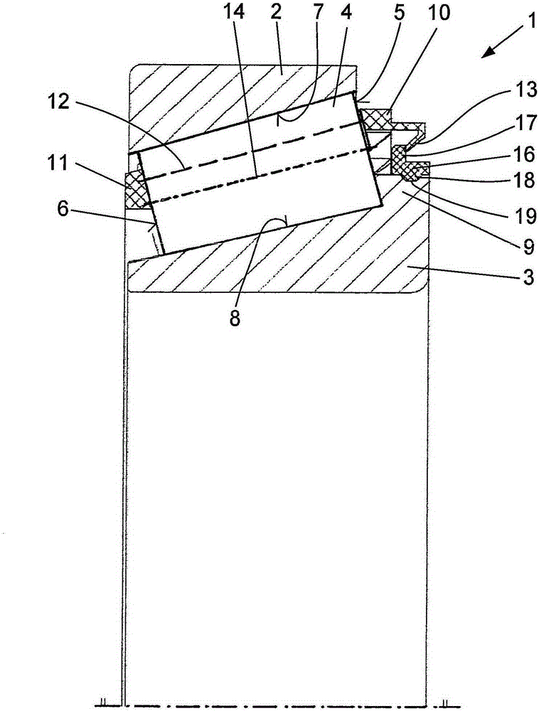
[0016] The tapered roller bearing 1 according to the invention consists of an outer bearing ring 2 and an inner bearing ring 3, between which tapered rollers 4 are guided in a cage rolling on the associated raceways 7, 8, the cage consisting of side Rings 10, 11 and webs 12 connecting them are shown schematically in dashed lines.

[0017] The tapered rollers 4 are supported with their large-diameter roller faces 5 on radial ribs 9 on the inner bearing ring 3 , while the small-diameter roller faces 6 rest only on the side rings 11 . The webs 12 indicated by dotted lines lie radially outside the axis of rotation 14 of the tapered rollers in order to arrange the tapered rollers 4 as close as possible to one another and to increase the number of tapered rollers 4 .

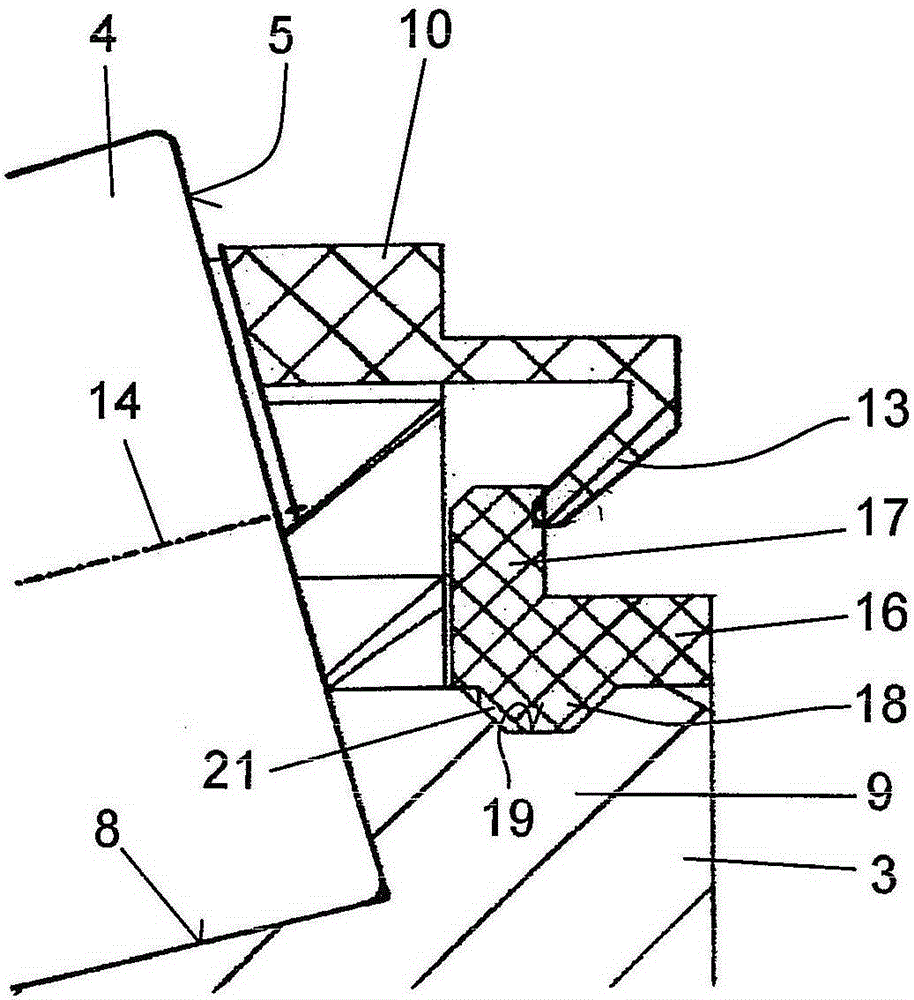
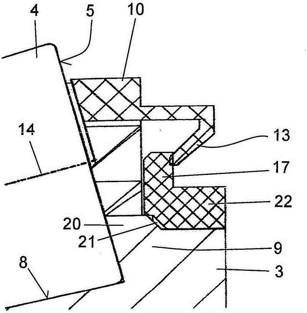
[0018] On the side ring 10 facing the roller end side 5 with the larger diameter are formed radially inwardly protruding projections 13 in the form of collets, which grip the guide ring axially from the rear. Beading...


PUM


Abstract

The invention relates to a tapered roller bearing (1), comprising two coaxial bearing rings (2, 3) and a plurality of tapered rollers (4) which are arranged between the bearing rings (2, 3) and guided in a cage (10, 11, 12) and roll off respective raceways (7, 8) on the bearing rings (2, 3), and further comprising a rim (9) at the large diameter of the inner bearing ring (3) for removing axial forces from the tapered rollers (4). At the large diameter, the cage (10, 11, 12) comprises elastic protrusions (13) which interact with the rim (9) and which axially preload the cage (10, 11, 12) with the tapered rollers (4) against the rim (9). According to the invention, the tapered roller bearing is designed such that a guide ring (16, 22) made of a material having a higher thermal expansion coefficient than the material of the rim (9) is arranged on the rim (9) by means of press fit, the elastic protrusions (13) of the cage (10, 11, 12) engage the guide ring (16, 22), and the press fit is dimensioned such that, in the event the press fit loosens due to the bearing heating up during operation, the guide ring (16, 22) becomes axially slidable, and thus the axial preload of the cage (10, 11, 12) with the tapered rollers (4) is cancelled.

Description

technical field [0001] The invention relates to a tapered roller bearing with two coaxial bearing rings and a plurality of tapered rollers arranged between the bearing rings and guided in a cage, the tapered rollers on the bearing rings The tapered roller bearing also has ribs at the large diameter of the inner bearing ring for deriving the axial force from the tapered rollers, wherein the cage has elastic protrusions at its large diameter These elastic projections cooperate with the ribs and pretension the cage together with the tapered rollers axially against the ribs. Background technique [0002] A tapered roller bearing of this type with a cage is described in DE4338350A1, wherein the cage is provided in the pocket with axial elastic means for pretensioning the relatively large ribs of the rollers at the small diameter, and at the large On the diameter there are projections which snap into grooves arranged on the inner bearing ring or snap into behind projections arran...

Claims


Application Information

Patent Timeline
Patent Type & Authority Patents(China)
IPC IPC(8): F16C33/46F16C33/58F16C19/34
CPCF16C33/4605F16C19/364F16C33/605F16C2300/02
Inventor 托尔斯滕·施莱格尔
Owner SCHAEFFLER TECH AG & CO KG
Why Eureka
Try Eureka