
Magnetic flow cytometry for individual

A magnetic flow and cell technology, applied in the field of flow-through blood cell counting, can solve the problem that positive signals cannot be uniquely traced back to a single cell, and achieve the effect of reducing background signals

Active Publication Date: 2013-05-08
SIEMENS AG
View PDF3 Cites 0 Cited by
  • Summary
  • Abstract
  • Description
  • Claims
  • Application Information

AI Technical Summary

Problems solved by technology

But the positive signal here cannot be uniquely traced back to a single cell

Method used


Image

  • Magnetic flow cytometry for individual
  • Magnetic flow cytometry for individual
  • Magnetic flow cytometry for individual

Examples


Embodiment Construction

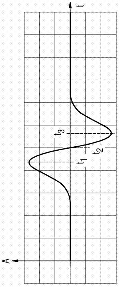
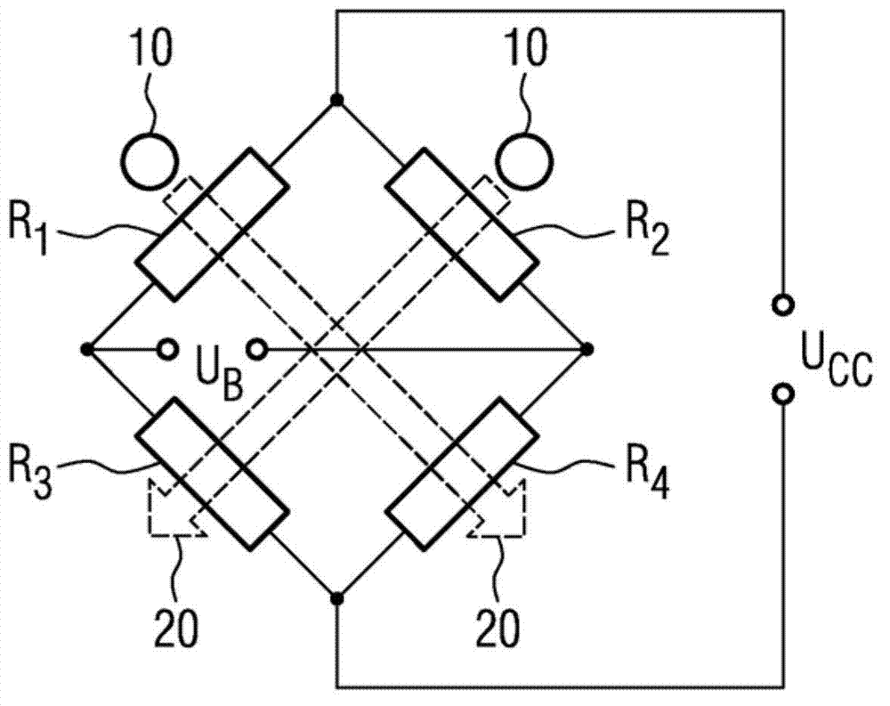
[0062] exist figure 1 The course of the measurement signal over time t shown in , firstly shows a positive measurement deflection and then a negative measurement deflection of the same magnitude A. This signal is formed when a single cell 10 moves via a single measuring resistor. Flow in time towards 20 in figure 2 shown in . figure 2 shows that at three instants t 1 , t 2 and t 3 of cells10. Cell 10 at time interval t 1 to t 3 in the measured resistance. Furthermore, the scattered field of the cell 10 is shown. Here, only the in-plane field (in-plane), ie the field parallel to the direction of motion indicated by the velocity arrow v, is registered by the measuring resistor. Fields perpendicular to the direction of motion and perpendicular to the plane in which the resistors lie are not picked up by the sensor. The external field for accumulating the cells 10 on the resistor is aligned exactly in this direction perpendicular to the direction of motion.

[0063]...


PUM

PropertyMeasurementUnit
diameteraaaaaaaaaa
diameteraaaaaaaaaa
diameteraaaaaaaaaa

Abstract

The invention relates to flow cytometry. The claimed method ensures precise individual cell detection and cell measurement of cells in the flow. A pair of magnetoresistive components are used to produce a characteristic measuring signal profile from which the following information can be obtained: number of measurement deviations, measurement deviation distances, measurement deviation amplitudes, measurement deviation direction and measurement deviation direction sequence. The flow speed and the cell diameter can also be determined. Also, the signal noise ratio can be determined using the measurement deviation amplitude.

Description

technical field [0001] The present invention relates to a flow-through blood cell count. Background technique [0002] Flow-through measurements are known in the field of cytometry and cell detection, in which a magnetically labeled analyte flows through a magnetic sensor. Here, however, the positive signal cannot be uniquely traced back to individual cells. Thus, cells incorrectly labeled by lateral selection of magnetic markers also give rise to positive signals. In addition, free markers can also cause positive signals. Cell aggregation in turn can only result in a positive signal and cannot be recognized per se. Contents of the invention [0003] The technical problem to be solved by the present invention is to reduce background signals and avoid false positive signals in magnetic flow cytometry. [0004] The aforementioned technical problem is solved by the method according to claim 1 and the device according to claim 9 . Developments of the method and advantageo...

Claims


Application Information

Patent Timeline
Patent Type & Authority Applications(China)
IPC IPC(8): G01N15/10
CPCG01N15/1031G01N27/72
Inventor O.海登M.J.赫卢S.F.特德
Owner SIEMENS AG
Learn More