
Metal chip centrifugal machine

A metal cutting and centrifuge technology, applied in the field of centrifuges, can solve the problems of oil pollution on the ground, residues, adverse effects on the factory environment, etc., and achieve the effect of improving the cleaning effect and reducing the residual amount.

Inactive Publication Date: 2013-05-15
JIANGSU HUJIANG CENTRIFUGE MFR
View PDF6 Cites 2 Cited by
  • Summary
  • Abstract
  • Description
  • Claims
  • Application Information

AI Technical Summary

Problems solved by technology

[0004] 2. A large amount of cutting oil or cutting fluid is mixed in metal cutting chips, which affects the quality, efficiency and price of metal recycling, and has a negative impact on the factory environment, and oil pollutes the ground
[0005] At present, a centrifuge is used on the market to separate the cutting oil on the metal chips. The cutting oil is separated from the metal chips by centrifugal force, and the cutting oil on the metal surface is separated and thrown out by the high-speed rotating basket in the centrifuge. One-time separation often cannot separate the cutting oil on the metal surface, and there is often a large amount of residue

Method used


Image

  • Metal chip centrifugal machine

Examples


Embodiment Construction

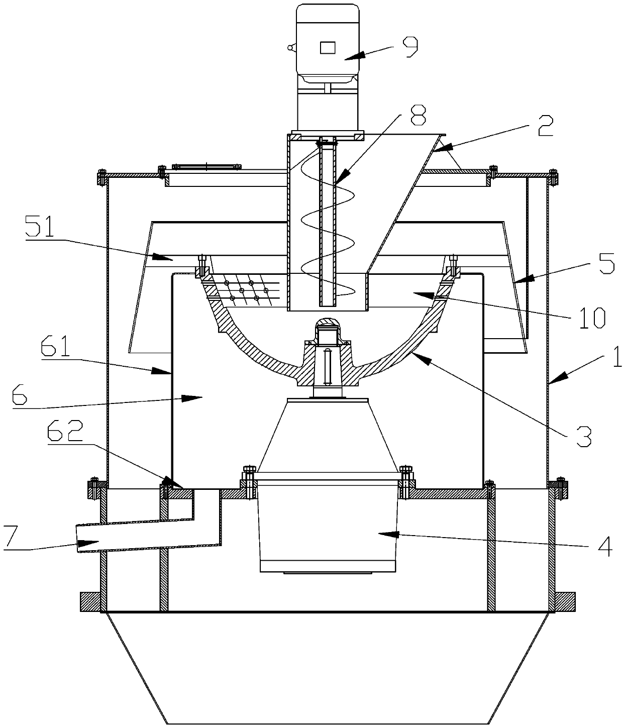
[0021] Such as figure 1 As shown, the metal swarf centrifuge of this embodiment includes a housing 1, the upper part of the housing 1 is provided with a hopper 2, and the lower part of the hopper 2 is provided with an inner basket 3 containing metal swarf to be cleaned. A motor 4 is connected to the bottom of the rotating basket 3 , and an outer rotating basket 5 is arranged on the outside of the inner rotating basket 3 , and the outer rotating basket 5 is fixed to the inner rotating basket 3 and moves with the inner rotating basket 3 .

[0022] In order to facilitate waste oil collection, in this embodiment, the inner basket 3 is provided with a closed cavity 6 outside, and the closed cavity 6 is connected to the outside of the housing 1 through an oil outlet pipe 7 .

[0023] In this embodiment, the inner basket 3 is a bowl-shaped opening upwards; the outer basket 5 is upside down on the inner basket 3; the outer basket 5 is provided with a horizontal annular partition 51, ...


PUM


Abstract

The invention relates to centrifugal machines, in particular to a metal chip centrifugal machine. The centrifugal machine comprises a shell body, a hopper is arranged on the upper portion of the shell body, an inward-turning basket used for containing metal chips to be cleared is arranged below the hopper, a motor is connected on the bottom portion of the inward-turning basket, an outward-turning basket is arranged outside the inward-turning basket, and the outward-turning basket is fixed with the inward-turning basket and moves along with the inward- turning basket. According to the metal chip centrifugal machine, the metal chip is thrown into the outward-turning basket to carry out a secondary separation after being separated in the inward-turning basket, and after the secondary separation, the metal chip is discharged. The cleaning effect of the cutting oil on the surface of the metal chip is improved, and a residual quantity is greatly reduced.

Description

technical field [0001] The invention relates to a centrifuge, in particular to a metal chip centrifuge. Background technique [0002] During the mechanical turning process of hardware parts, a large amount of metal cutting chips, such as metal chips, aluminum chips, copper chips, etc., will be produced. These metal chips will adhere to a large amount of metal cutting oil or cutting fluid. If these iron scraps, aluminum scraps, copper scraps and other metal scraps are not deoiled and dehydrated, the following problems will be caused: [0003] 1. A large amount of consumption and waste of metal cutting oil and cutting fluid. If the cutting oil and cutting fluid in metal cutting chips are recycled and used, it will help customers in the field of mechanical turning to greatly reduce the loss of metal cutting oil and cutting fluid. manufacturing cost; [0004] 2. A large amount of cutting oil or cutting fluid is mixed in metal cutting chips, which affects the quality, efficienc...

Claims


Application Information

Patent Timeline
Patent Type & Authority Applications(China)
IPC IPC(8): B04B1/00B04B7/08B04B11/04
Inventor 李伟
Owner JIANGSU HUJIANG CENTRIFUGE MFR
Learn More