
Material pushing piece of drum of material pushing centrifugal machine

A technology for centrifuges and ejectors, applied in the field of centrifuges, can solve the problems of high cost of use, easy wear and tear of ejectors and screens, and achieve the effects of prolonging service life, low cost, and convenient disassembly and assembly.

Active Publication Date: 2013-05-15
ZHEJIANG QINGJI CENTRIFUGE MFG
View PDF11 Cites 5 Cited by
  • Summary
  • Abstract
  • Description
  • Claims
  • Application Information

AI Technical Summary

Problems solved by technology

[0003] The purpose of the present invention is to solve the problem of easy wear and high cost between the pusher sheet and the screen in the existing pusher centrifuge, and provide a reasonable structure, which adopts a single piece of wear-resistant non-metallic material, and is always in operation. The push piece on the drum of the push centrifuge that is close to the screen and has little wear

Method used


Image

  • Material pushing piece of drum of material pushing centrifugal machine
  • Material pushing piece of drum of material pushing centrifugal machine
  • Material pushing piece of drum of material pushing centrifugal machine

Examples


Embodiment Construction

[0023] The technical solutions of the present invention will be further specifically described below through the embodiments and in conjunction with the accompanying drawings.

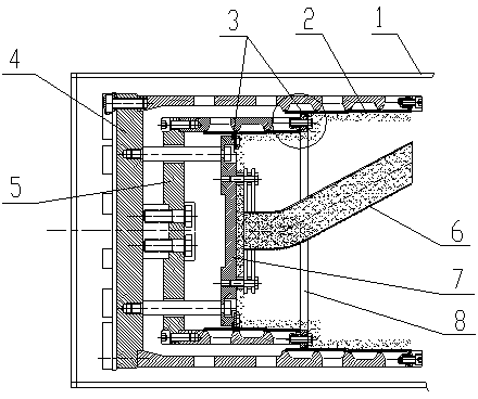
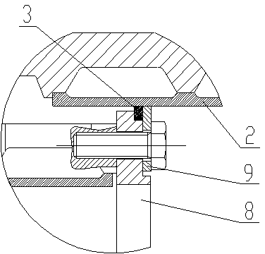
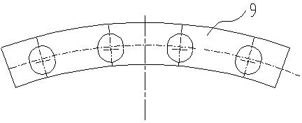
[0024] In this embodiment, a pusher piece on the drum of a pusher centrifuge is applied to the leak-proof position between the screen 2 and the baffle 7 and the screen 2 and the pusher ring 8 in the centrifuge drum, such as figure 1 , figure 2 As shown, in combination with the baffle plate 7 and the pusher ring 8, the pusher piece is used in combination of two parts, one is an arc-shaped pressing piece 9, such as image 3 As shown, the other is a convex monolithic 3, such as Figure 4 shown.

[0025] Wherein, the arc-shaped pressing sheet 9 is an arc section made of metal material, and its length is one-eighth of a full circle. The outer arc of this arc section is equal to the inner diameter of the screen 2 where the inner baffle plate 7 of the rotating hub is assembled. Each arc-shaped pressing pi...


PUM


Abstract

The invention relates to the technical field of centrifugal machines, in particular to a material pushing piece of a drum of a material pushing centrifugal machine. The problems that a material pushing piece and a screening sieve are easily abraded and use cost is high in an existing material pushing centrifugal machine are solved. The material pushing piece of the drum of the material pushing centrifugal machine is characterized by comprising an arc press piece and a nose single piece. The arc press piece is an arc segment of a steel complete round and provided with threaded holes. The nose single piece is provided with an arc segment made of polyether-ether-ketone or polytef materials. Three protruded bodies are arranged on a place facing the center of the arc segment and the size of each protruded body is matched with a groove gap arranged in a material pushing ring of the drum. The arc press piece is matched with the nose single piece in length. During the centrifugal machine works for a long time, the centrifugal machine is tightly adhered to the screen sieve, whereas the screen sieve is not abraded. Materials are prevented from moving to the bottom of the drum and service life of the drum of the centrifugal machine is greatly prolonged.

Description

technical field [0001] The invention relates to the technical field of centrifuges, in particular to a material pushing piece on a drum of a material pushing centrifuge. Background technique [0002] The pusher centrifuge is a continuous operation filter centrifuge, which uses the high-speed rotation of the drum to generate strong centrifugal force and the filtering and separating effect of the screen to achieve the purpose of separating and dehydrating the processed solid-liquid mixture. The existing metal material pusher used in conjunction with the screen, if it is close to the screen, the screen is easy to wear, which will increase the production cost. If the pusher and the screen maintain a certain gap, it is easy to leak material, so that the material goes to the screen. The movement of the bottom of the drum may easily cause accumulation of material at the bottom of the drum, which will affect the normal operation of the drum, and corrosive materials will easily enter...

Claims


Application Information

Patent Timeline
Patent Type & Authority Applications(China)
IPC IPC(8): B04B7/08
Inventor 沈盛波王刘波
Owner ZHEJIANG QINGJI CENTRIFUGE MFG
Learn More