Drilling tail end actuator

A technology of end effector and inner hole, which is applied in the direction of manufacturing tools, boring/drilling, drilling/drilling equipment, etc. It can solve problems such as difficult to process with aviation components and large axial force, and achieve convenient transmission design , Reduce the axial force of hole making and reduce the difficulty of design

Active Publication Date: 2013-05-15
江苏欧亿德新材料科技有限公司
View PDF10 Cites 24 Cited by
  • Summary
  • Abstract
  • Description
  • Claims
  • Application Information

AI Technical Summary

Problems solved by technology

For different hole diameters, the drilling end effector needs to be equipped with a large number of tool changing links; and the axial force is relatively large during drilling, which makes it difficult for the drilling end effector to be used for deep thickness and large hole diameter machining of aviation components

Method used


Image

  • Drilling tail end actuator
  • Drilling tail end actuator
  • Drilling tail end actuator

Examples


Embodiment Construction

[0037] The specific embodiments of the present invention will be further described below in conjunction with the accompanying drawings.

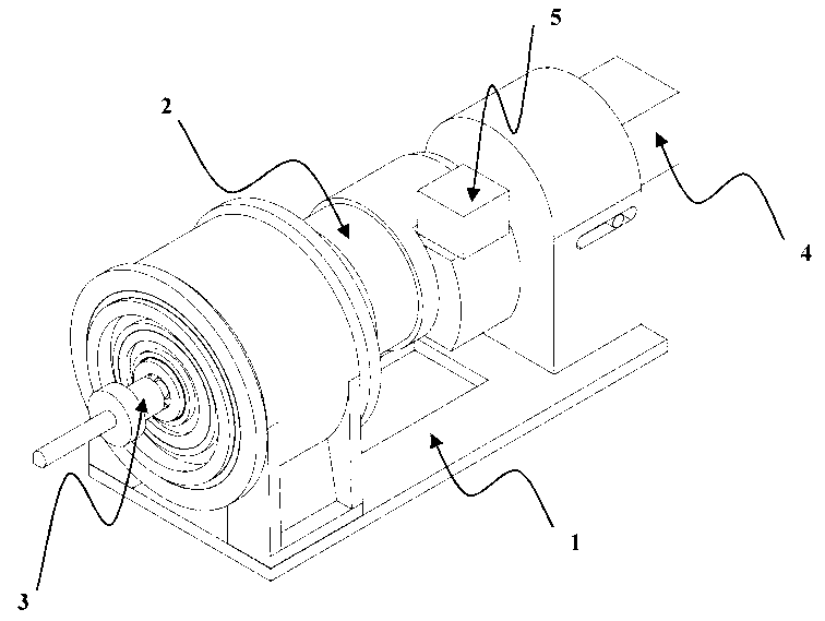
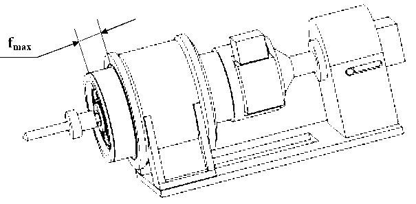
[0038] Such as figure 1 and figure 2 The shown hole-making end effector includes a docking support assembly 1, a tool revolution assembly 2 arranged at one end of the docking support assembly 1, a tool rotation assembly 3 provided in the tool revolution assembly 2, and a tool rotation assembly 3 arranged at the other end of the docking support assembly 1. One end is used to control the axial feed assembly 4 of the tool axial feed and the tool deviation adjustment assembly 5 arranged on the tool revolution assembly 2 for eccentric adjustment of the tool, wherein figure 1 Indicates the state where the axial feed of the tool is zero, figure 2 Indicates that the tool is in the state of maximum axial feed, and the maximum feed is f in the figure max .

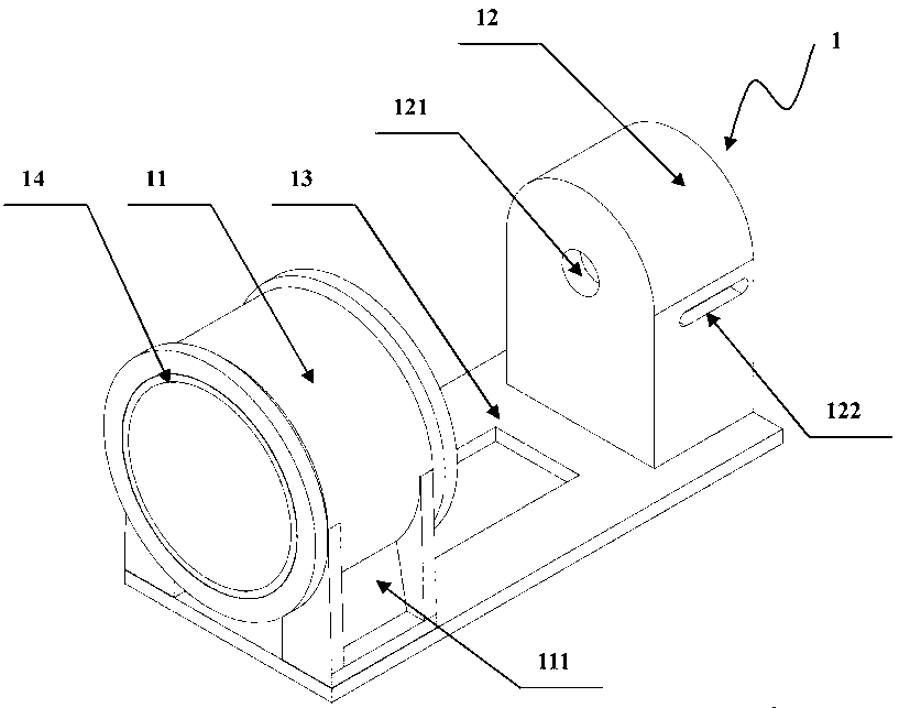
[0039] Such as image 3 As shown, the docking support assembly 1 includes a base plate ...


PUM


Abstract

The invention discloses a drilling tail end actuator which comprises a butt joint support assembly, a cutter revolution assembly arranged at one end of the butt joint support assembly in a rotation mode, a cutter rotation assembly arranged in the cutter revolution assembly in a rotation mode, an axial feeding assembly arranged at the other end of the butt joint support assembly and used for controlling axial feeding of a cutter, and a cutter deviation adjusting assembly arranged on the cutter revolution assembly and used for performing deviation adjustment on the cutter. The drilling tail end actuator has the advantages that the cutter deviation adjusting assembly is arranged so that the drilling tail end actuator clamps the cutter capable of machining various apertures, a cutter changing link is avoided, and drilling efficiency is improved. The cutter revolution assembly and the cutter rotation assembly are arranged so that double functions of drilling and milling holes in a screwed mode of the drilling tail end actuator are achieved. Externally exposed arrangement of the cutter deviation adjusting assembly is achieved so that transmission design among moving components is convenient, and the design difficulties of the drilling end tail actuator are reduced.

Description

technical field [0001] The invention discloses a hole-making end effector, relates to a high-efficiency hole-making end effector suitable for automatic and continuous processing of different hole diameters, and belongs to the field of robot cutting. Background technique [0002] With the continuous development of the working performance of the robot body and its control technology, the robotized automatic hole-making system is widely used in the aviation assembly manufacturing industry due to its advantages of automation, flexibility, and low cost. In order to achieve high-efficiency and precise hole-making of aviation components, some new robotized automatic hole-making systems are emerging at home and abroad, such as automatic hole-making systems based on crawling robots, automatic hole-making systems based on articulated industrial robots, and automatic hole-making systems based on flexible rails. hole system. [0003] As an important part of the robotic automatic hole m...

Claims


Application Information

Patent Timeline
Patent Type & Authority Applications(China)
IPC IPC(8): B23B39/10B23B47/00
Inventor 单以才施泽波舒平生李亮何宁杨吟飞章婷李一民
Owner 江苏欧亿德新材料科技有限公司
Why Eureka
Try Eureka