Tapping machine

A technology of tapping machine and body, applied in the field of tapping machine, can solve the problems of shortening the service life, affecting the service life and machining accuracy, insufficient moving speed, etc., and achieving the effects of prolonging the service life, easy maintenance and improving convenience.

Inactive Publication Date: 2013-05-15
SHANGHAI LIANG LIH MACHINERY & ELECTRIC CO LTD
View PDF10 Cites 10 Cited by
  • Summary
  • Abstract
  • Description
  • Claims
  • Application Information

AI Technical Summary

Problems solved by technology

[0004] Although the above-mentioned method can make the empty stroke of the knife advance and retract move quickly, it needs to drive the rack through the worm gear regardless of manual feed or automatic feed. To meet the needs of fast movement, at the same time, the connection and drive of the mechanism will cause wear of the components, which will affect its subsequent service life and processing accuracy
In addition, the main components of the existing tapping machine are all installed inside the machine body, which is a closed design, so it is extremely inconvenient to assemble, and when there is a need for maintenance and replacement of parts, there are also many troubles and even damage. , Invisibly increase the maintenance cost and shorten its service life
[0005] The reason is that the inventor aims at the problem that the moving speed of the aforementioned tapping machine is limited and easy to wear and difficult to disassemble when advancing and retracting the empty stroke, based on years of experience in related industries, and actively seeks a solution. Through hard research and development, we finally successfully invented a tapping machine to overcome the troubles and inconveniences caused by insufficient moving speed, easy wear, and difficult disassembly and assembly.

Method used


Image

  • Tapping machine
  • Tapping machine
  • Tapping machine

Examples


Embodiment Construction

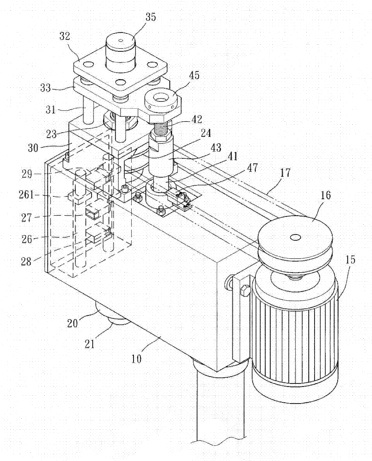
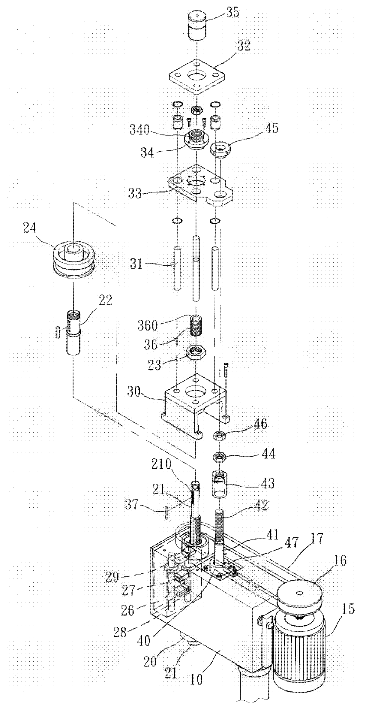
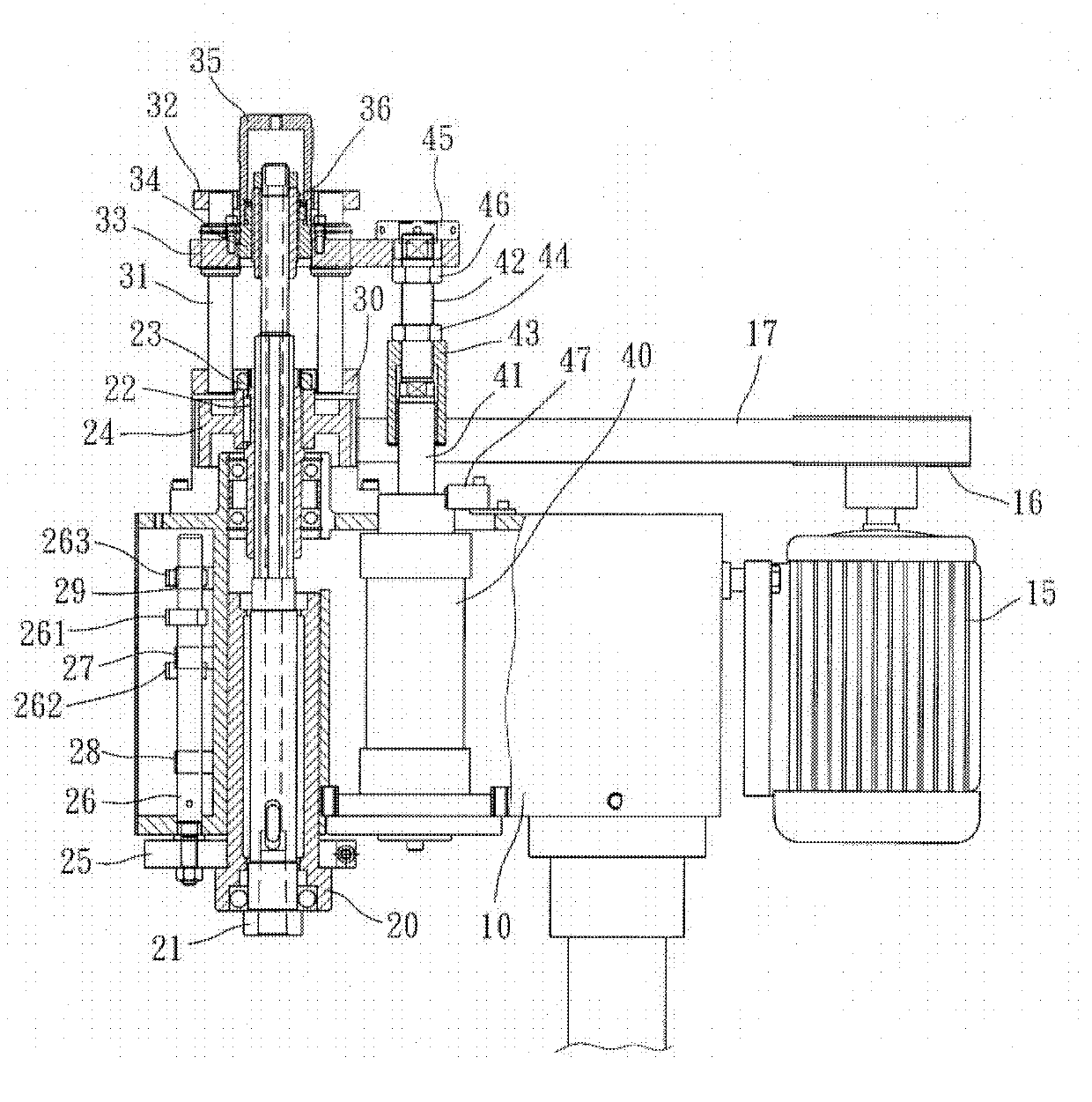
[0051] For the detailed composition of the tapping machine of the present invention, please refer to figure 1, figure 2 , Figure 3A and Figure 3B As shown, the tapping machine has a body 10, the body 10 is provided with a main shaft 20 that can move up and down, and the inner pivot of the main shaft 20 is provided with a rotating shaft 21 that can rotate and move synchronously, and one end of the body 10 is provided with a controllable The driving element 15 of rotating speed and steering, wherein the driving element 15 can be selected from servo motors and stepper motors that can control the rotating speed and steering. The output end of the driving element 15 has a pulley 16 for driving the aforementioned main shaft 20 through at least one belt 17 The axis of rotation 21;

[0052] The middle section of the rotating shaft 21 of the main shaft 20 is provided with a shaft sleeve 22 pivotally arranged on the body 10, wherein the inner edge of the shaft sleeve 22 forms an i...


PUM


Abstract

A tapping machine is provided with a machine body, the machine body is provided with a main shaft capable of up-down movement, a rotary shaft capable of rotation and synchronous movement is pivoted in the main shaft, one end of the machine body is provided with a driving element capable of controlling rotation speed and rotation direction; a rotary shaft middle section of the main shaft is provided with a shaft sleeve pivoted on the machine body; the machine body is provided with a fixed seat for going-through of an upper end of the rotary shaft corresponding to the upper part of the main shaft; a cylinder body is disposed in the machine body, and the cylinder body is provided with a telescopic rod capable of rising and falling due to gas pressure or oil pressure source. The tapping machine is easy to disassemble, relative components are exposed, maintenance, component change and detachment assembly of the tapping machine are facilitated, stability and accuracy of action are improved, service lifetime is prolonged, rapid movement can be performed, movement time of knife feeding and retracting idle running can be shortened, unnecessary abrasion is reduced, and machining accuracy is ensured.

Description

technical field [0001] The invention relates to a feed driving technology of a tapping machine, in particular to a tapping machine capable of quick action in an empty stroke, which further has the convenience of disassembly and maintenance. Background technique [0002] The general tapping machine is mainly improved from the drilling machine. Its operation process: first, let the spindle move the tapping tool to the top of the workpiece [commonly known as the empty stroke of the tool]. Then, make the tapping knife rotate and feed at a slow speed to perform the tapping action [generally called the working stroke of the knife]. Afterwards, after the predetermined working depth is completed, the tapping tool is reversed and withdrawn from the workpiece [generally referred to as the retracting working stroke]. Finally, let the spindle drive the tapping tool back to its original position [generally called the empty stroke of tool retraction]. [0003] In order to take into acco...

Claims


Application Information

Patent Timeline
Patent Type & Authority Applications(China)
IPC IPC(8): B23G1/18B23G1/44
Inventor 周凯文
Owner SHANGHAI LIANG LIH MACHINERY & ELECTRIC CO LTD
Why Eureka
Try Eureka