

Silicon carbide monocrystal cutting line positioning method
A cutting line and crystal technology, which is applied in the field of silicon carbide single crystal cutting line positioning, can solve the problem of high cost and achieve the effect of low cost and high precision
- Summary
- Abstract
- Description
- Claims
- Application Information
AI Technical Summary
Problems solved by technology
Method used
Image

Examples
Embodiment 1
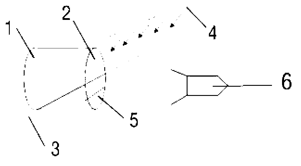
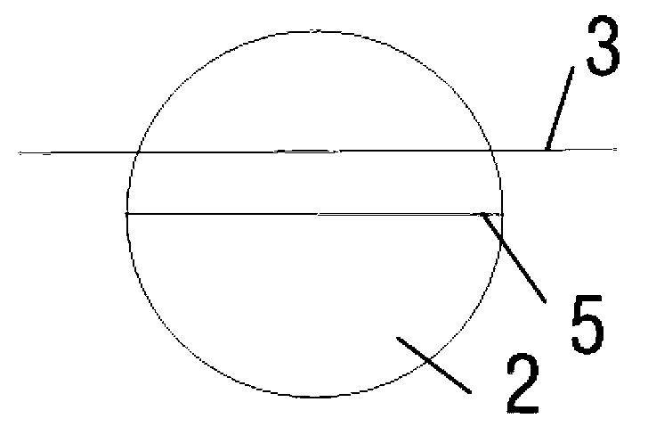
[0022] 1) Fix the cylindrical silicon carbide crystal 1 on the stage, the diameter of the crystal is 50.8mm, polish any bottom surface of the crystal, and adjust the position of the crystal 1 on the stage so that the cutting line 3 is in line with the polished bottom surface 2 parallel, a line light source 4 is arranged directly in front of the polished bottom surface 2, the line light source 4 is parallel to the cutting line 3, and is consistent with the relative position of the cutting line 3;
[0023] 2) An image acquisition camera 6 is installed directly in front of the polished bottom surface 2 and facing the cutting line 3 to collect images of the polished bottom surface 2, cutting line 3, and shadow line 5 in real time;
[0024] 3) Adjust the crystal in the horizontal direction: adjust the cutting line 3 to 1 / 3 from the top to the bottom directly in front of the polished bottom surface 2, the cutting line 3 is 5mm away from the crystal, the line light source 4 illuminate...
Embodiment 2
[0028] 1) Fix the cylindrical silicon carbide crystal 1 on the stage, the diameter of the crystal is 76.2mm, polish any bottom surface of the crystal 1 to make it smooth, and adjust the position of the crystal 1 on the stage so that the cutting line 3 is in line with the polished The bottom surface 2 is parallel, and a line light source 4 is arranged directly in front of the polished bottom surface 2, the line light source 4 is parallel to the cutting line 3, and is consistent with the relative position of the cutting line 3;
[0029] 2) An image acquisition camera 6 is installed directly in front of the polished bottom surface 2 and facing the cutting line 3 to collect images of the polished bottom surface 2, cutting line 3, and shadow line 5 in real time;
[0030] 3) Adjust the crystal in the horizontal direction: adjust the cutting line 3 to 1 / 3 from the top to the bottom directly in front of the polished bottom surface 2, the distance between the cutting line 3 and the crys...
Embodiment 3
[0034] 1) Fix the cylindrical silicon carbide crystal 1 on the stage, the diameter of the crystal is 101.6mm, polish any bottom surface of the crystal 1 to make it smooth, and adjust the position of the crystal 1 on the stage so that the cutting line 3 is in line with the polished The bottom surface 2 is parallel, and a line light source 4 is arranged directly in front of the polished bottom surface 2, the line light source 4 is parallel to the cutting line 3, and is consistent with the relative position of the cutting line 3;
[0035] 2) An image acquisition camera 6 is installed directly in front of the polished bottom surface 2 and facing the cutting line 3 to collect images of the polished bottom surface 2, cutting line 3, and shadow line 5 in real time;
[0036] 3) Adjust the crystal in the horizontal direction: adjust the cutting line 3 to 1 / 3 from the top to the bottom directly in front of the polished bottom surface 2, the cutting line 3 is 10mm away from the crystal, t...
PUM
 Abstract
Description
Claims
Application Information