Electric equipment for railway vehicle

A technology for railway vehicles and electrical products, applied in locomotives, railway transportation, railway transportation, etc., can solve the problems of increased stress and deflection of the installation part, and achieve the effects of preventing mass increase, solving strength, and relaxing stress.

Active Publication Date: 2013-05-15
HITACHI LTD
View PDF6 Cites 2 Cited by
  • Summary
  • Abstract
  • Description
  • Claims
  • Application Information

AI Technical Summary

Problems solved by technology

However, when the mounting position is provided at a position other than the partition plate 7a, 7b or the end in the traveling direction, the load sharing deflection of the suspension increases, and the stress on the mounting portion may increase.

Method used


Image

  • Electric equipment for railway vehicle
  • Electric equipment for railway vehicle
  • Electric equipment for railway vehicle

Examples


Embodiment Construction

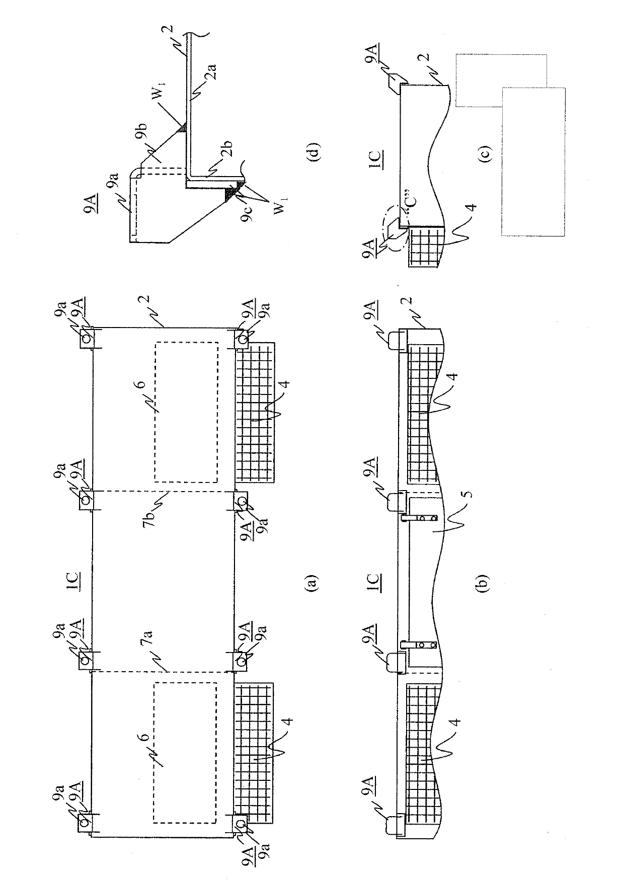
[0070] Below, use Figure 1 to Figure 4 , and an embodiment of an electrical product for railway vehicles to which the present invention is applied will be described. It should be noted that, in the following description, the same functional components are assigned the same symbols and repeated descriptions are omitted.

[0071] figure 1 It is a figure which shows the 1st embodiment of the electric product for railway vehicles of this invention, (a) is a top view, (b) is a front view, (c) is a right side view, (d) is C part enlargement of (c) picture. exist figure 1 in, with Figure 8 and Figure 9 The difference lies in the structure of the suspension equipment, others with Figure 8 and Figure 9 same.

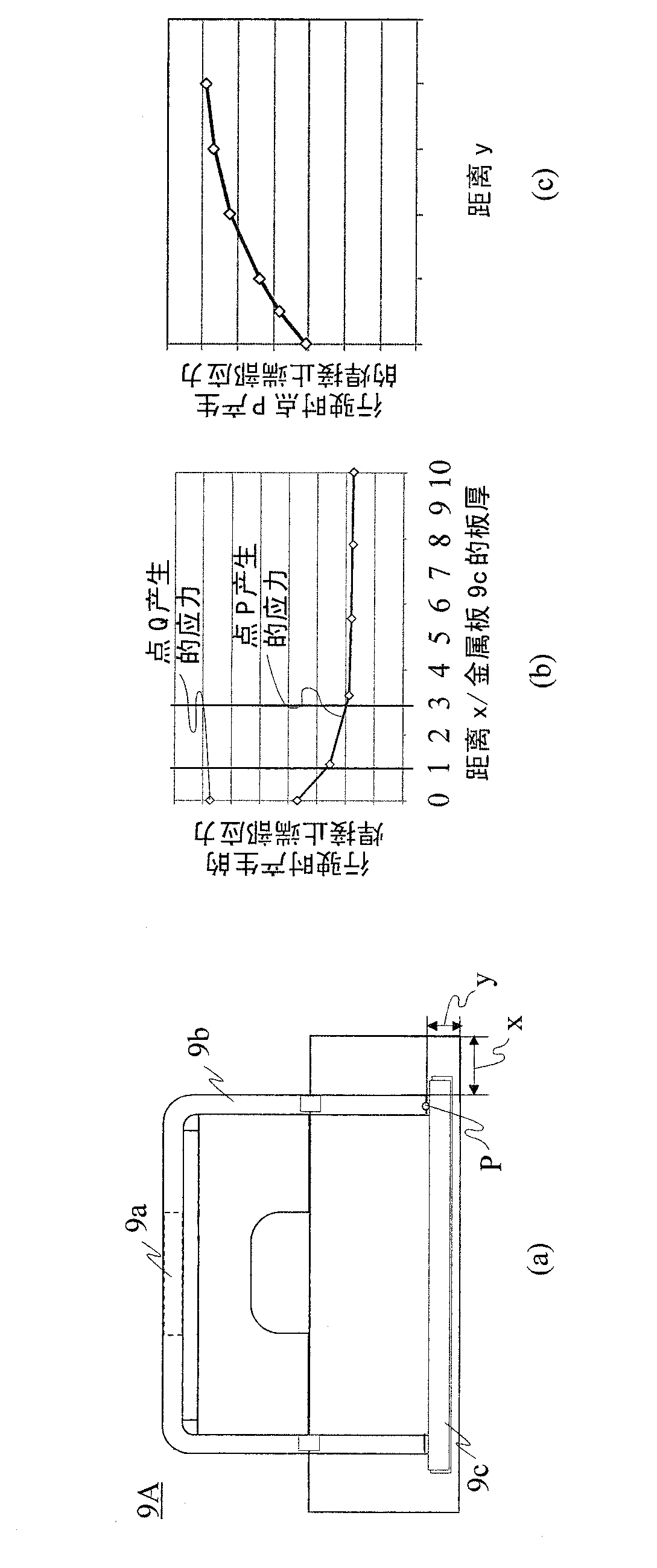
[0072] The hanger 9A is comprised from the hanger 9b and the metal plate 9c. Hanger 9b in figure 1 In the front view of (b), the metal plate is bent into an inverted U shape, has bent mounting portions on both sides and an upper portion connecting the mounting p...


PUM


Abstract

In electric equipment for railway vehicle, a hanging structure which is capable of accommodating a limitation in mounting position on the vehicle side without increasing the mass or the number of components and changing the arrangement of electric equipment in a box is provided. A hanging part having an integrated structure in which a hanging part (9A) having a shape accommodating limitations in mounting position on the vehicle side in the direction of crosstie and in the vertical direction is joined to a metallic plate (9C) is joined to a ceiling plate (2a) and a side plate (2b) of a box member (2) at a position corresponding to the limitation in mounting position in the direction of travel of the vehicle side. The electric equipment for railway vehicle is hung from a beam under a floor of the vehicle via a bolt hole provided on an upper portion of the hanging part.

Description

technical field [0001] The present invention relates to electrical products for railway vehicles. Background technique [0002] Figure 5 It is an explanatory diagram showing a structure in which an electric product to which the present invention is applied is equipped on a body of a railway vehicle. [0003] A curtain rail 30 parallel to the traveling direction K of the vehicle is fixed to the lower surface of the floor of the vehicle body 20 , and the electric product 1 is mounted on the curtain rail 30 . [0004] Figure 6 The state where the electric product 1 is attached to the curtain rail 32 fixed parallel to the sleeper direction L of the vehicle body 20 is shown. Arrow M indicates the up-down direction of the vehicle body. [0005] Figure 7 express Figure 5 The detail of the main part of 2 shows the state in which the electric product 1 is hung on the curtain rail 30 via the hanging tool 40 with respect to the traveling direction. [0006] Figure 8 (a) is a...

Claims


Application Information

Patent Timeline
IPC IPC(8): B61C17/00
CPCB61C17/06Y02T30/18Y02T30/00
Inventor 井上刚志堀野正也渡边克美西连寺一宏
Owner HITACHI LTD
Why Eureka
Try Eureka