Static weft insertion structure

A technology of static electricity and static electricity generator, applied in textile, textile and papermaking, looms, etc., can solve the problem of high energy consumption and achieve the effect of reducing the power of weft insertion

Inactive Publication Date: 2013-05-15
WUJIANG LANRUITE TEXTILE
View PDF6 Cites 1 Cited by
  • Summary
  • Abstract
  • Description
  • Claims
  • Application Information

AI Technical Summary

Problems solved by technology

[0003] Because the air-jet loom adopts the air-flow weft method, because the weft yarn is light in texture, a strong airflow is required to send the weft yarn into the weft filling device, resulting in the biggest disadvantage of the air-jet loom: high energy consumption

Method used


Image

  • Static weft insertion structure

Examples


Embodiment 1

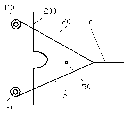
[0014] refer to figure 1 , in this embodiment, the electrostatic weft insertion structure includes an upper warp feed beam 110 and a lower warp feed beam 120 respectively arranged on the upper and lower parts of the frame, and the upper warp feed beam 110 and the lower warp feed beam 120 convey two strands The weft threads 20, 21 are interwoven into a "V" shaped shed, which accommodates the weft threads 50 from the air nozzle, which is electrically connected to an electrode of an electrostatic generator, the warp beam 120 and the warp beam 120. The air nozzle is connected to the same electrode of the electrostatic generator.

[0015] In the above electrostatic weft insertion structure, the air nozzle and the lower let-off beam 120 are connected to the negative electrode of the electrostatic generator, which is beneficial to absorb positive ions in the air, increase the content of negative ions in the air, and protect the health of textile workers.

Embodiment 2

[0017] refer to figure 1 , in this embodiment, the electrostatic weft insertion structure includes an upper warp feed beam 110 and a lower warp feed beam 120 respectively arranged on the upper and lower parts of the frame, and the upper warp feed beam 110 and the lower warp feed beam 120 convey two strands The weft threads 20, 21 are interwoven into a "V" shaped shed, which accommodates the weft threads 50 from the air nozzle, which is electrically connected to an electrode of an electrostatic generator, the warp beam 120 and the warp beam 120. The air nozzle is connected to the same electrode of the electrostatic generator.

[0018] In the above-mentioned electrostatic weft insertion structure, the upper warp delivery beam 110 is electrically connected to the electrostatic generator, and the polarity of the electrode connected to it is opposite to that of the electrode connected to the air nozzle and the lower warp delivery beam 120,

[0019] In summary, the charge generated...


PUM


Abstract

The invention provides a static weft insertion structure which comprises a nozzle, an upper warp sending beam and a lower warp sending beam which are respectively arranged on the upper portion and the lower portion of a machine frame. The upper warp sending beam and the lower warp sending beam deliver two strands of wefts which form a V-shaped shed in an interwoven mode, the shed contains wefts coming from an air nozzle which is electrically connected with an electrode of an electrostatic generator, the lower warp sending beam and the air nozzle are connected with the same electrode of the electrostatic generator, the static weft insertion structure uses interaction force among electrostatic charges, the wefts are enabled to overcome gravitational force, air injection power of the air nozzle is effectively reduced, and electric energy is saved.

Description

technical field [0001] The invention relates to the field of shuttleless looms, in particular to a weft insertion structure with low power consumption. Background technique [0002] The shuttleless loom is a new type of loom that was born after the shuttle loom. Shuttleless looms quickly occupied the loom market due to their light weight, low vibration, low noise, fast speed, and high efficiency. The air-jet loom is a shuttleless loom that uses jet air to pull the weft through the shed. The working principle is to use the air as the weft insertion medium, and use the compressed air jet to generate friction and traction on the weft yarn to pull the weft yarn through the shed, and achieve the purpose of weft insertion through the jet generated by the air jet. This weft insertion method enables the loom to achieve high speed and high production. Among several shuttleless looms, the air-jet loom is the one with the highest speed. Due to the reasonable weft insertion method, h...

Claims


Application Information

Patent Timeline
IPC IPC(8): D03D47/00
Inventor 赵萍
Owner WUJIANG LANRUITE TEXTILE
Why Eureka
Try Eureka