
Shear type expansion anchor rod and extension application thereof

A technology of expanding anchor rods and expansion plates, which is applied in the direction of installing anchor rods, sheet pile walls, pins, etc., can solve problems such as increased labor intensity, poor pull-out resistance, and damage to stable layers, and achieves simple and ingenious structure, convenient and reliable use , The effect of easy processing and manufacturing

Inactive Publication Date: 2013-05-15
裴志胜
View PDF2 Cites 32 Cited by
  • Summary
  • Abstract
  • Description
  • Claims
  • Application Information

AI Technical Summary

Problems solved by technology

[0003] 1. Expansion tubular anchors and expansion shell anchors. Due to their own structural defects, the opening and closing degree and stiffness of the expansion end of the anchor head and the force after expansion are limited due to their own structural defects. The stable solid layer realizes reliable expansion consolidation or locking, poor pull-out resistance, weak suspension and clamping force;
[0004] 2. In order to make up for the above defects, there have been grouting anchors and injection expansion anchors. This type of anchor is made by stringing together a number of loose or fragmented layers and filling the gaps with slurry and increasing the anchorage and anchorage. The overall friction of the matrix hole wall realizes the so-called "composite beam" or "arch effect". State solid layer), taking a step back, even if the so-called "composite beam" or "arch effect" can be expected to work, the clamping force that strings loose or fragmented layers together still requires strong opening and closing and rigidity of the expansion end of the anchor rod , otherwise the nut at the end of the anchor cannot tighten them, and the anchor can only function as a "pin". The so-called "composite beam" or "arch effect" created in this way is a bit self-deceiving;
[0005] 3. In order to solve the problem of anchor head consolidation, people have developed the adhesive method. Obviously, it is very difficult to try to rely on adhesives to solve the problem of "rooting" of the anchor (rooting is the connection between the head of the anchor and The firm and reliable consolidation or locking of the elastic zone of the matrix or the stable solid layer), especially for the suspension or permanent anchoring of the upper part of the surrounding rock or must reflect the immediate anchoring effect (the adhesive needs a curing period) or the adhesive When the application environment is harsh (such as wet or soft sandstone layer or hole cleaning is not clean), etc., not to mention the negative reaction of the adhesive to different application objects and service life is unpredictable;
[0006] 4. In order to make up for the inability to "take root" or the unreliability of "rooting", people have adopted the method of increasing the anchoring density to distribute the weight or displacement force of the loose layer to more anchor rods, which greatly increases the labor intensity. , reduced work efficiency and construction progress, and greatly increased the overall cost. However, the problem of "rooting" the anchor rod has not been resolved. , it is a temporary solution rather than a permanent cure, and if it is not done well, it will disturb or destroy the surrounding stable layer

Method used


Image

  • Shear type expansion anchor rod and extension application thereof
  • Shear type expansion anchor rod and extension application thereof
  • Shear type expansion anchor rod and extension application thereof

Examples


Embodiment Construction

[0031] Below in conjunction with accompanying drawing and specific implementation for further description:

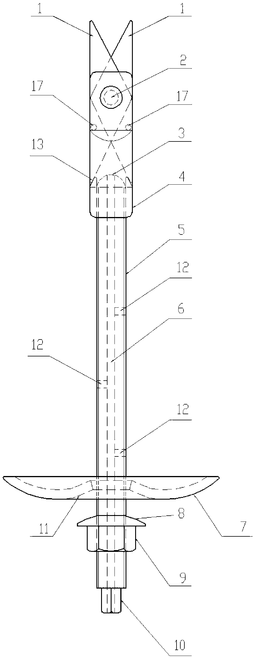
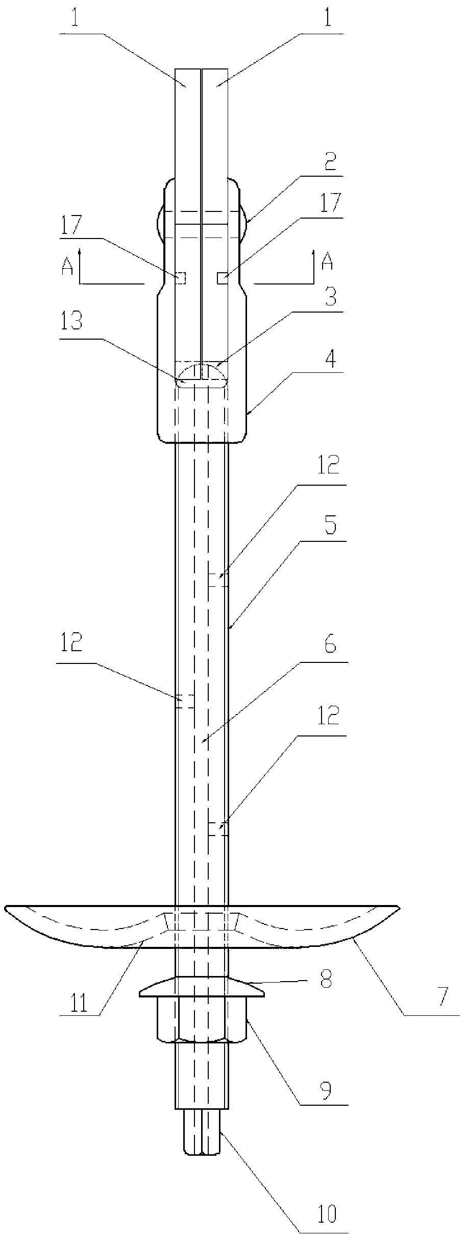
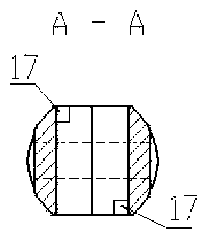
[0032] Referring to the accompanying drawings, the fixing part of the present invention is a lug nut support (4), and the lug nut support has two opposite support plates, and hinge holes are arranged on the upper part of the support plate; the expansion part is two An expansion plate (1), the two expansion plates are combined and embedded between the two support plates of the lug nut support, and are hinged with the support plate; the pusher is a screw rod matched with the lug nut support ( 5), the arc surface (3) at the top of the screw is in contact with the lower ends of the two expansion plates, and rotating the screw can directly push the two expansion plates outwards along the slope of the lower end of the expansion plate; of course , the threads on the screw can be full threads, or only threads are provided at both ends of the screw.

[0033] Limiting steps (13)...


PUM


Abstract

The invention provides a shear type expansion anchor rod which comprises a fixing part, a pushing part and a tightening part, wherein the fixing part is provided with an expansion part. The shear type expansion anchor rod is characterized in that the pushing part is matched with the fixing part, the pushing part and the fixing part can move along the coaxial direction of the axis of the fixing part, the expansion part is hinged with the top end portion of the fixing part, the lower end portion of the expansion part is provided with an inclined surface facing the pushing part, the top end portion of the pushing part can contact with the inclined surface of the lower end portion of the expansion part and pushes the expansion part along the inclined surface, the expansion part is stretched in a shear mode towards the outer side of the pushing part, and the tightening part is arranged at the lower end of the pushing part and can move in the coaxial direction of the axis of the pushing part. The shear type expansion anchor rod is simple and ingenious in structure, the expansion part is stretched in the shear mode, the stretched range is large, anchoring force is strong, and the shear type expansion anchor rod not only is used for surrounding rock support and protection, but also is widely suitable for anchoring or fixation of mines, tunnels, protection slops, foundation trenches, buildings and other engineering. Extension application comprises underpinnings for constructing the buildings, stand columns for highway sides, and the like, and safety, reliability and universal values of the shear type expansion anchor rod are achieved really.

Description

technical field [0001] The invention relates to an anchor rod in the technical field of anchoring, in particular to a scissor expansion anchor rod, including extended applications. Background technique [0002] In the implementation of mines, tunnels, slope protection, foundation pits, dams and other projects, it has become an application trend to use anchor bolts to reinforce loose and unstable layers, and it is also very popular in academia, such as those appearing on the market or recorded in existing patent documents There are: [0003] 1. Expansion tubular anchors and expansion shell anchors. Due to their own structural defects, the opening and closing degree and stiffness of the expansion end of the anchor head and the force after expansion are limited due to their own structural defects. The stable solid layer realizes reliable expansion consolidation or locking, poor pull-out resistance, weak suspension and clamping force; [0004] 2. In order to make up for the a...

Claims


Application Information

Patent Timeline
Patent Type & Authority Applications(China)
IPC IPC(8): E21D21/00E02D5/74E02D5/54E01F15/02E02D27/42F16B13/10
Inventor 裴志胜裴春光
Owner 裴志胜
Learn More