Water storage tank and water storage type water heater applying the same

A water storage tank and water tank technology, which is applied to fluid heaters, lighting and heating equipment, etc., can solve the problems of inability to flexibly adjust the hot water capacity of the water tank, low hot water utilization rate, and no capacity expansion function, etc. The effect of reducing heat energy waste and saving materials

Active Publication Date: 2013-05-15
GREE ELECTRIC APPLIANCES INC
View PDF6 Cites 10 Cited by
  • Summary
  • Abstract
  • Description
  • Claims
  • Application Information

AI Technical Summary

Problems solved by technology

[0002] The existing water storage water heater is mainly composed of a heat exchanger, a water pump and a water storage tank. The water pump pumps a small part of water to the heat exchanger to heat up, and then returns to the water storage tank. In this way, all the water in the water storage tank is heated. There are the following problems: (1) Heating the water stored in the entire water tank cannot flexibly adjust the hot water capacity of the water tank according to the number of people who use the water, and when the hot water is used up, it must wait until all the cold water in the water tank is heated before it can be used again Hot water, long waiting time; (2) When a few people use water, the hot water in the entire water tank cannot be used up, and there is a problem of waste of heat energy; (3) The utilization rate of hot water is low, there is no capacity expansion function, and a large-capacity water tank is required to Meeting water demand, high cost and waste of resources

Method used


Image

  • Water storage tank and water storage type water heater applying the same
  • Water storage tank and water storage type water heater applying the same
  • Water storage tank and water storage type water heater applying the same

Examples


Embodiment 1

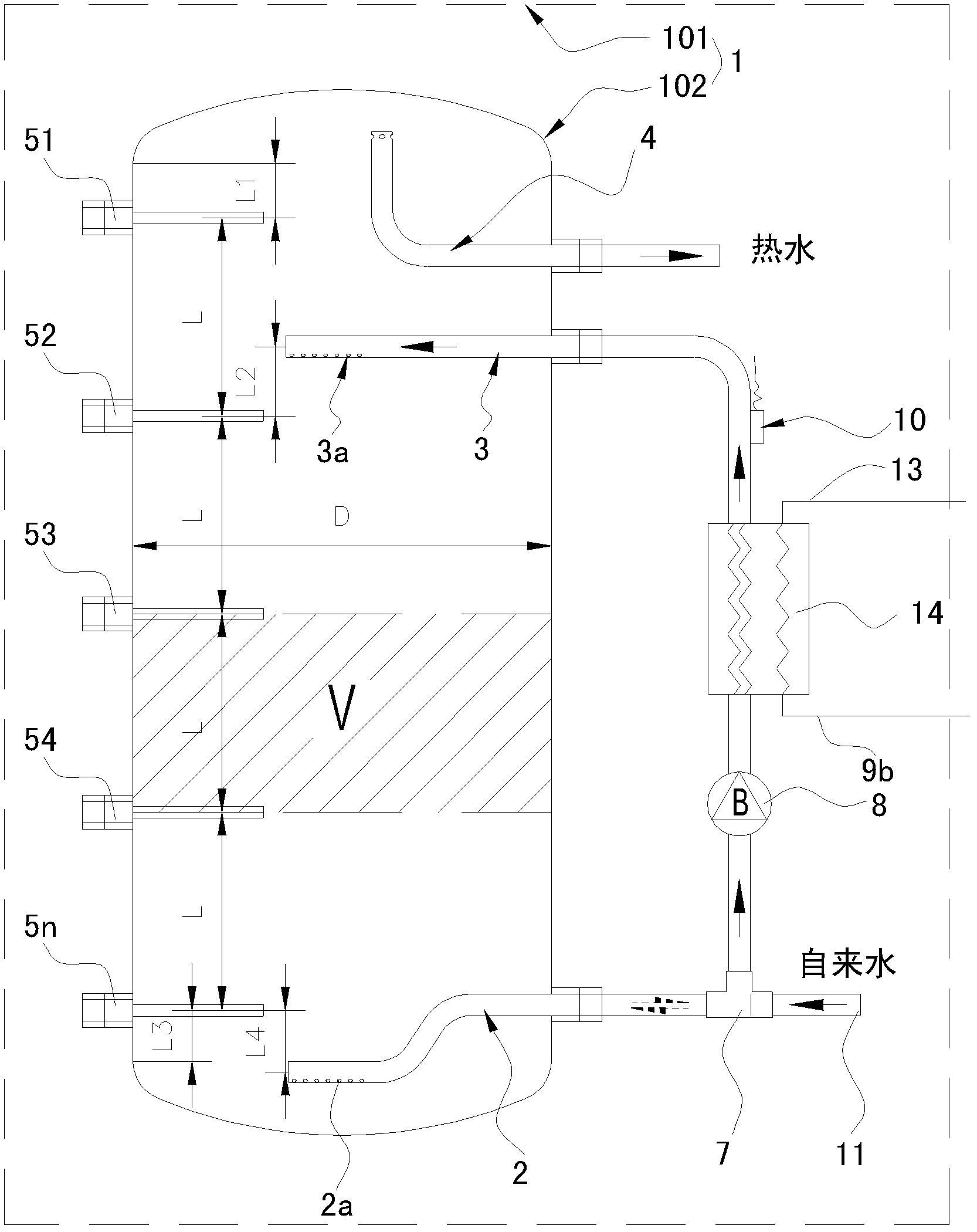
[0030] See figure 1 , the water storage tank 1 is mainly composed of a water tank shell 101, a water tank liner 102, a circulating water inlet pipe 3, a circulating water outlet pipe 2, a cold water inlet pipe 11, a hot water outlet pipe 4, a frequency conversion water pump 8 and a heat exchanger 9. The tank 102 is in the shape of a cylinder. A circulating water inlet pipe 3 and a hot water outlet pipe 4 are arranged on the upper part of the water tank inner tank 102. Five temperature sensing packages (ie temperature sensors) 51 , 52 , 53 , 54 , 5n for detecting the temperature at different positions in the water tank liner 102 are provided, and the temperature sensing packages are inserted into the water tank liner 102 .

[0031] In order to accurately detect the outlet water temperature of the water tank liner 102, the position of the temperature sensing package 51 with the highest height should be located on the top of the water tank liner 102 as much as possible. In order...

Embodiment 2

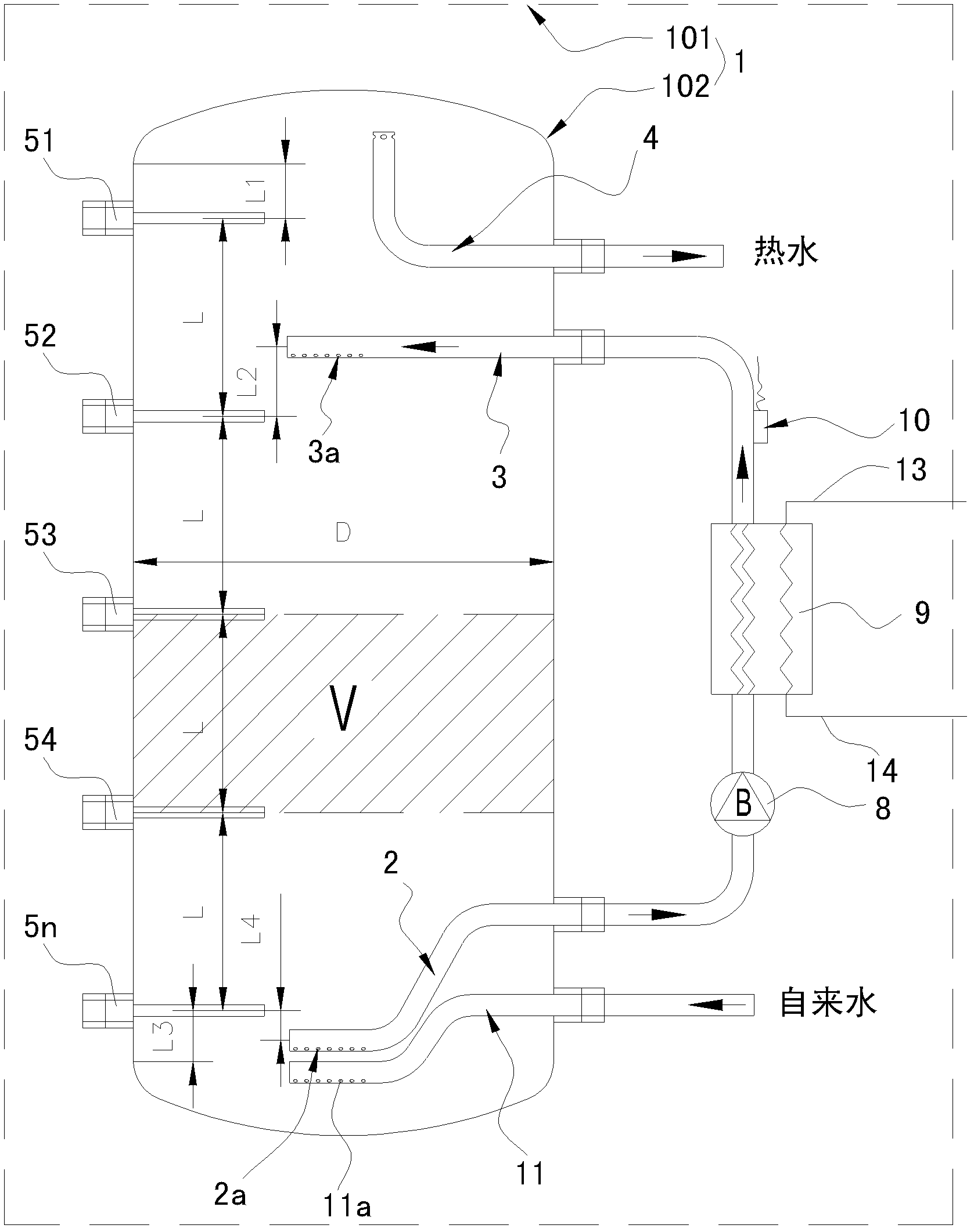
[0046] See image 3 , and the difference from Embodiment 1 is that the temperature sensing package is attached to the outer wall of the water tank liner 102, and the water inlet of the water pump 8 is directly connected to the second end of the circulating water outlet pipe 2. The cold water inlet pipe 1111 is arranged on the water tank liner 102 below the circulating water outlet pipe 2. The first end of the cold water inlet pipe 1111 extends into the water tank liner 102, and the mouth of the first end is closed. The lower part of the pipe wall is provided with a through hole 11a. In the water storage tank of this embodiment, the cold water inlet pipe 11 and the circulating water outlet pipe 2 are arranged separately, so that the cold water supply and the direct heating of the water at the bottom of the water tank can be sent to the top of the water tank at the same time, which better reflects the capacity increase effect.

Embodiment 3

[0048] See Figure 4 , different from Embodiment 2, this embodiment has two water tank liners 102a, 102b, and the two water tank liners 102a, 102b are connected in series through the connecting pipe 6 from front to back according to the water flow direction, and the first connecting pipe 6 One end stretches into the bottom of the previous water tank liner 102a, and its second end stretches into the top of the rear water tank liner 102b. The circulating water inlet pipe 3 and the hot water outlet pipe 4 are arranged on the top of the front water tank liner 102a. The water outlet pipe 2 is located at the bottom of the last water tank liner 102b, and the water tank liner 102 is also provided with 4 temperature sensors 51, 52, 53, 54 for detecting the temperatures at different positions in the water tank liner 102 respectively.

[0049] The water storage tank 1 adopting a plurality of water tank liners 102 in series has the following benefits: (1) the mode of connecting a pluralit...


PUM


Abstract

The invention discloses a water storage tank which comprises a water tank liner, a circulating water inlet pipe, a circulating water outlet pipe, a cold water inlet pipe and a hot water inlet pipe, the number of the water tank liner is one, the circulating water inlet pipe and the circulating water outlet pipe are respectively arranged at the upper portion of the water tank liner, the circulating water outlet pipe is arranged at the lower portion of the water tank liner, the water tank liner is further provided with at least three temperature sensors which are used for respectively detecting temperatures at different positions inside the water tank liner, or the number of the water tank liners are two, the water tank liners are sequentially in tandem connection through connecting pipes from front side to back side along the direction of water flow, and each water tank liner is further provided with the temperature sensors which are used for detecting the temperatures at different positions inside each water tank liner. Due to the facts that the water storage tank adopts a pattern of heating from top to bottom and meanwhile the temperatures are feed back through a plurality of temperature sensors which are arranged from top to bottom, flexible adjustment of the volume of hot water in the water storage tank is achieved and requirements of different numbers of people who uses the water are met. Meanwhile, the invention further discloses a water storage type water heater applying the water storage tank.

Description

technical field [0001] The present invention relates to a water storage tank for a water heater, and a storage type water heater using the water storage tank. Background technique [0002] The existing water storage water heater is mainly composed of a heat exchanger, a water pump and a water storage tank. The water pump pumps a small part of water to the heat exchanger to heat up, and then returns to the water storage tank. In this way, all the water in the water storage tank is heated. There are the following problems: (1) Heating the water stored in the entire water tank cannot flexibly adjust the hot water capacity of the water tank according to the number of people who use the water, and when the hot water is used up, it must wait until all the cold water in the water tank is heated before it can be used again Hot water, long waiting time; (2) When a few people use water, the hot water in the entire water tank cannot be used up, and there is a problem of waste of heat e...

Claims


Application Information

Patent Timeline
Patent Type & Authority Applications(China)
IPC IPC(8): F24H9/00
Inventor 董明珠谭建明李绍斌柳飞袁明征曹浩
Owner GREE ELECTRIC APPLIANCES INC
Why Eureka
Try Eureka