Intellectualized design method facing machine tool strut member ribbed slab layout with high specific stiffness

A design method and support technology, applied in computing, special data processing applications, instruments, etc., can solve problems such as low design efficiency, inability to realize intelligence and automation, and inability to obtain high specific stiffness design solutions, so as to achieve performance improvement, The effect of meeting the design requirements of high rigidity ratio

Inactive Publication Date: 2013-05-15
XI AN JIAOTONG UNIV
View PDF0 Cites 2 Cited by
  • Summary
  • Abstract
  • Description
  • Claims
  • Application Information

AI Technical Summary

Problems solved by technology

In the design process of the existing heavy-duty and super-heavy-duty manufacturing equipment load-bearing structures, most of them adopt the traditional arrangement of ribs, mainly in the form of well-shaped, rice-shaped, or a combination of the above forms. The design form is too single to obtain high-quality Specific stiffness design scheme
At the same time, the existing rib layout design methods mainly rely on classical mechanics and the experience of designers. After repeated revisions to obtain the final plan, the entire design process cannot be intelligent and automated, resulting in low design efficiency and cannot meet the needs of modern large-scale and complex equipment. design requirements

Method used


Image

  • Intellectualized design method facing machine tool strut member ribbed slab layout with high specific stiffness
  • Intellectualized design method facing machine tool strut member ribbed slab layout with high specific stiffness
  • Intellectualized design method facing machine tool strut member ribbed slab layout with high specific stiffness

Examples


Embodiment Construction

[0034] The present invention will be further described below in conjunction with accompanying drawings and examples.

[0035] According to the present invention, the intelligent design method for the rib plate layout of the machine tool supports with high specific stiffness is as follows: figure 1 As shown, it includes the following design stages and specific steps:

[0036] 1. Design stage 1: Construction of pseudo-3D generative space model

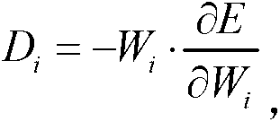
[0037] Firstly, the original solid structure of the machine tool support is simplified as a combination of internal ribs and peripheral panels. Next, the above-mentioned simplified combination is further abstracted into a pseudo-three-dimensional space model, which is composed of shell elements simulating the outer wall panels of the support and Matrix27 elements simulating the internal ribs of the support. According to the load-bearing relationship of the support, a peripheral wall plate is selected as the load-bearing surface, and a ...


PUM


Abstract

The invention discloses an intellectualized design method facing machine tool strut member ribbed slab layout with high specific stiffness. The intellectualized design method facing the machine tool strut member ribbed slab layout with the high specific stiffness specificly comprises preprocessing, self-adaptation generating and postprocessing, wherein the preprocessing comprises the following step: constructing virtual three-dimensional generating space model of a machine tool strut member; the self-adaptation generating comprises the following step; obtaining optimal layout of projecting of a machine tool strut member inner ribbed slab layout on a bearing surface; the postprocessing comprises the following steps: conducting stretch processing on projection configuration of the machine tool strut member bearing surface along an assigned direction; and then obtaining layout designing scheme of the machine tool strut member inner ribbed slab layout. By constructing a self-adaptation generating criterion of the bearing configuration, intellectualized design method facing the machine tool strut member ribbed slab layout with the high specific stiffness can achieve high specific stiffness design of the machine tool strut member, meet requirements of low carbon and saving materials, and can be widely used in optimal design of heavy type and extra-heavy type manufacturing equipment bearing configuration.

Description

technical field [0001] The invention belongs to a method for optimizing the design of bearing parts of heavy-duty and super-heavy manufacturing equipment, in particular to an intelligent design method for the rib plate layout of machine tool supports facing high specific stiffness. Background technique [0002] The current low-carbon, environmentally friendly and efficient production methods have prompted people to continue to make in-depth thinking about how to better realize the "low-carbon turn" in the development process of heavy and super-heavy manufacturing equipment, and this thinking just vividly reflects People's comprehensive performance requirements for key structures such as CNC machine tool supports have undergone a profound change from the "high rigidity level" in the sense of deformation in the past to the "high rigidity ratio level" in the sense of low carbon in the future. In the design process of the existing heavy-duty and super-heavy-duty manufacturing eq...

Claims


Application Information

Patent Timeline
Patent Type & Authority Applications(China)
IPC IPC(8): G06F19/00
Inventor 李宝童洪军邱志惠王哲琳闫素娜张浩
Owner XI AN JIAOTONG UNIV
Why Eureka
Try Eureka