A desulfurization device for purifying gas

A desulfurization device and technology for gas purification, which are applied in the fields of gas fuel, combustible gas purification, liquid scrubbing gas purification, etc., can solve the problems of high construction cost and operating energy consumption, achieve the benefits of residence time, promote mixing effect, and improve gas-liquid transfer. The effect of mass area

Active Publication Date: 2016-11-30
BEIJING SJ ENVIRONMENTAL PROTECTION & NEW MATERIAL CO LTD
View PDF10 Cites 0 Cited by
  • Summary
  • Abstract
  • Description
  • Claims
  • Application Information

AI Technical Summary

Problems solved by technology

[0006] In order to solve the problem of high construction cost and high energy consumption in operation of the desulfurization device used to remove high-sulfur concentration gas in the prior art, a low-cost construction, low energy consumption in operation and high desulfurization efficiency are provided. Desulfurization device for purifying gas

Method used


Image

  • A desulfurization device for purifying gas
  • A desulfurization device for purifying gas
  • A desulfurization device for purifying gas

Examples


Embodiment 1

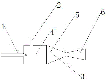
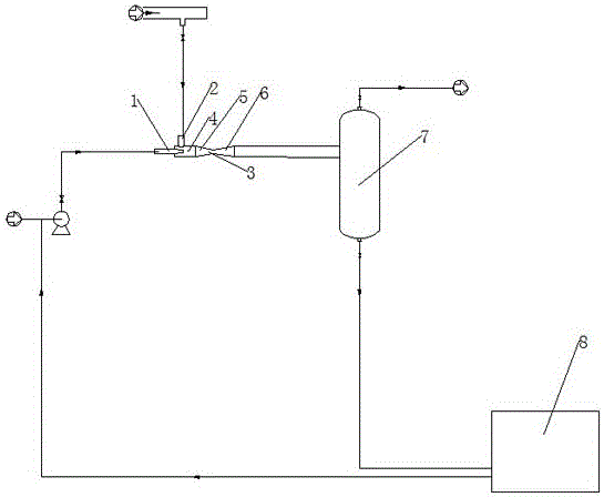
[0037] The desulfurization device described in this embodiment includes: a desulfurizer 3 and a gas-liquid separator 7 .

[0038] Such as figure 1 As shown, the desulfurizer 3 is sequentially provided with a buffer zone 4, a front-end convergence zone 5 and a rear-end diffusion zone 6 along the lateral direction. Nozzle 1, and the atomizing nozzle 1 is set close to the center of the buffer zone 4, and an air outlet is arranged in the rear-end diffusion area 6; in the front-end convergence area 5, the spray nozzle 1 The showering direction is perpendicular to the air intake direction of the air inlet 2; wherein, the buffer zone 4 is a cylinder with a constant diameter, and the front-end convergence zone 5 is a frustum-shaped cylinder that gradually shrinks along the gas flow direction, The contraction ratio of the front-end convergence zone 5 is 1:3; the rear-end diffusion zone 6 is a frustum-shaped cylinder gradually expanding along the gas flow direction, and the expansion r...

Embodiment 2

[0043] The desulfurization device described in this embodiment includes: a desulfurizer 3 and a gas-liquid separator 7 .

[0044] The desulfurizer 3 is sequentially provided with a buffer zone 4, a front convergence zone 5, a middle throat zone 9, and a rear diffusion zone 6 along the transverse direction. An atomizing nozzle 1, and the atomizing nozzle 1 is arranged near the center of the buffer zone 4, and an air outlet is arranged in the rear-end diffusion area 6; in the front-end convergence area 5, the atomizing nozzle 1 The spraying direction is perpendicular to the air intake direction of the air inlet 2; wherein, the buffer zone 4 is a cylinder with a constant diameter; the front end convergence zone 5 is a frustum-shaped cylinder that gradually shrinks along the gas flow direction body, the contraction ratio of the front-end convergence zone 5 is 1:3; the middle throat zone 9 is a cylindrical body with a constant diameter, that is, the diameter of the middle throat zo...

Embodiment 3

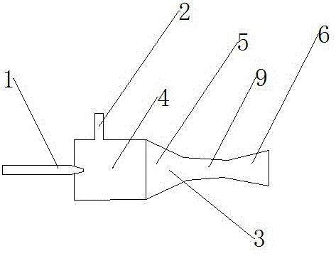
[0049] The desulfurization device described in this embodiment includes: a desulfurizer 3 and a gas-liquid separator 7 .

[0050] Such as figure 2 As shown, the desulfurizer 3 is sequentially provided with a buffer zone 4, a front convergence zone 5, a middle throat zone 9, and a rear diffusion zone 6 along the transverse direction. The buffer zone 4 is provided with an air inlet 2 and a The atomizing nozzle 1 of the desulfurization slurry, and the atomizing nozzle 1 is set close to the center of the buffer zone 4, and an air outlet is arranged in the rear-end diffusion area 6; in the front-end convergence area 5, the mist The spraying direction of the nozzle 1 is perpendicular to the air intake direction of the air inlet 2; wherein, the buffer zone 4 is a cylindrical body with a constant diameter; A frustum-shaped cylinder, the shrinkage ratio of the front-end convergence area 5 is 1:5; the middle throat area 9 is a frusto-conical cylinder that gradually shrinks along the g...


PUM

PropertyMeasurementUnit
diameteraaaaaaaaaa
particle diameteraaaaaaaaaa

Abstract

The invention relates to a desulfurization device, comprising a desulfurizer and a gas-liquid separator. The desulfurizer is sequentially connected with a buffer zone, a front-end convergence zone and a rear-end diffusion zone along the lateral direction, and an air inlet and a rear-end diffusion zone are arranged in the buffer zone. The liquid nozzle for spraying desulfurization slurry is provided with an air outlet in the rear diffusion area; the front convergence area is a cylinder gradually shrinking along the gas flow direction, and the rear diffusion area is gradually expanding along the gas flow direction cylinder; the ratio of the length of the buffer zone, the front-end convergence zone and the rear-end diffusion zone along the transverse direction is 3-5:4-6:3-5; the gas-liquid separator is provided with a gas outlet and a liquid The gas-liquid separator is connected to the gas outlet of the rear diffusion zone through a pipeline. The desulfurization device of the present invention has low construction cost, low operating energy consumption and high desulfurization efficiency.

Description

technical field [0001] The invention belongs to the field of gas purification, and in particular relates to a desulfurization device. Background technique [0002] h 2 S is a toxic, harmful and highly corrosive impurity widely present in coke oven gas, water gas, natural gas, biogas, crude synthesis gas, etc. 2 When the above gas of S is used as fuel, the H in it 2 S and its combustion product SO 2 All of them are toxic substances, which will cause environmental pollution. Therefore, the above-mentioned gases must be desulfurized and purified before being used as fuel. [0003] In order to ensure the effect of desulfurization, the prior art is used to remove H 2 The desulfurization device of S is usually equipped with packing or other desulfurization components, such as in the Chinese scientific and technological literature "Structure Improvement and Application of Desulfurization Tower in Crude Syngas Purification System" (August 2007, Big Nitrogen Fertilizer, Volume 30...

Claims


Application Information

Patent Timeline
Patent Type & Authority Patents(China)
IPC IPC(8): B01D53/78B01D53/80B01D53/52C10K1/08C10K1/10C10L3/10
Inventor 林科张旭之李廷均
Owner BEIJING SJ ENVIRONMENTAL PROTECTION & NEW MATERIAL CO LTD
Why Eureka
Try Eureka