Steel wire ring positioning clamping rotating device of steel wire ring winding machine

A wire ring winding machine, positioning and clamping technology, applied in the direction of manufacturing rings from wires, other household appliances, household appliances, etc., to achieve the effect of not easy to be damaged, easy to produce and simple in structure

Active Publication Date: 2013-05-22
哈尔滨工大宏图橡塑科技有限公司
View PDF10 Cites 10 Cited by
  • Summary
  • Abstract
  • Description
  • Claims
  • Application Information

AI Technical Summary

Problems solved by technology

[0003] The purpose of the present invention is to solve the problem that the traveler made by the existing traveler winding machine is formed by winding a steel wire in the forward direction. The steel wires a

Method used


Image

  • Steel wire ring positioning clamping rotating device of steel wire ring winding machine
  • Steel wire ring positioning clamping rotating device of steel wire ring winding machine
  • Steel wire ring positioning clamping rotating device of steel wire ring winding machine

Examples


Embodiment Construction

[0016] The present invention will be further described in detail below with reference to the drawings: this embodiment is implemented on the premise of the technical solution of the present invention, and detailed implementation manners are given, but the protection scope of the present invention is not limited to the following embodiments.

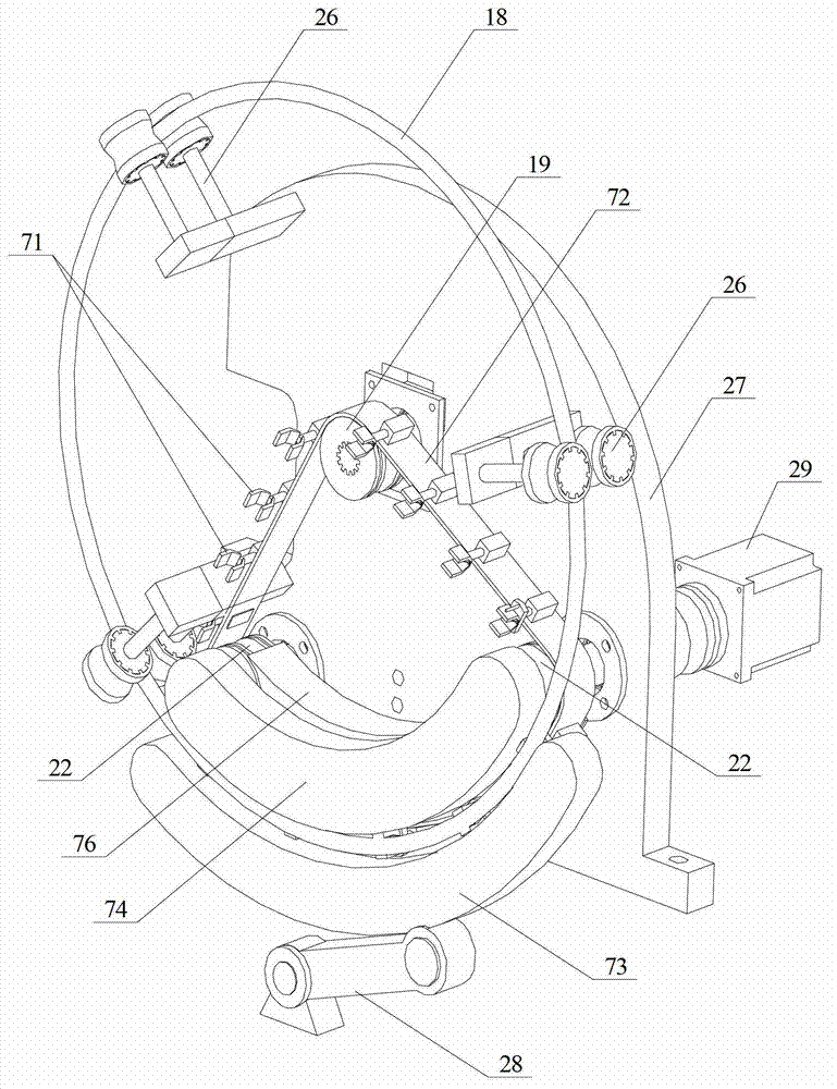
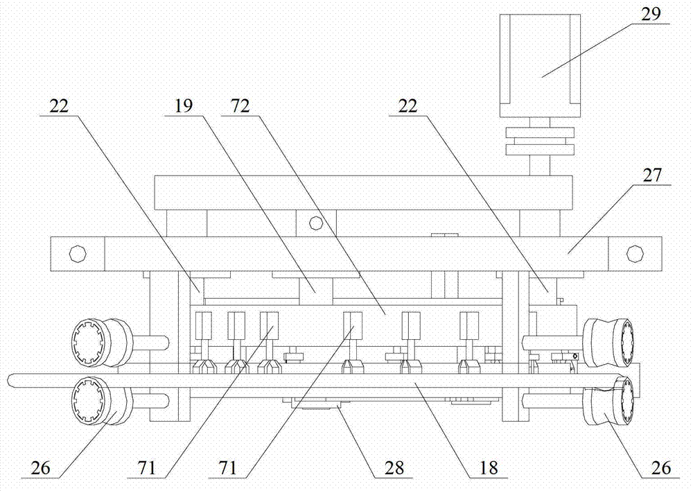
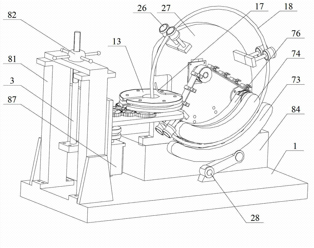
[0017] Such as figure 1 with figure 2 As shown, the traveler positioning, clamping and rotating device of the traveler winding machine involved in this embodiment includes: a central roller 19, two driving rollers 22, three pairs of auxiliary rollers 26, a rear machine plate 27, and a hydraulic cylinder 28 , Drive roller drive motor 29, mechanical claw 71, steel belt 72, lower guide steel plate 73, upper guide steel plate 74 and support steel plate 76. The three pairs of auxiliary rollers 26 are arranged on the rear machine plate 27, and the support steel plate 76 is fixed at the back At the lower part of the front side of the machine plate ...


PUM


Abstract

The invention provides a steel wire ring positioning clamping rotating device of a steel wire ring winding machine and belongs to the technical field of rotating devices. The device is characterized in that three pairs of help rollers are arranged on a rear machine plate, a steel band is in transmission connection with a central roller and two transmission rollers respectively and provided with a manipulator, an upper-portion guide steel plate is fixed on a supporting steel plate, a lower-portion guide steel plate is arranged on the lower portion of the upper guide steel plate, and the lower end of the lower-portion guide steel plate is connected with a hydraulic cylinder. The steel wire ring positioning clamping rotating device is simple in structure and easy to produce and manufacture, rotating directions of steel wires between an inner layer and an outer layer of a wound steel wire ring, the steel wire on one layer rotates leftwards while the steel wire on the other layer rotates rightwards, filling of rubber between the steel wires is not needed, shearing force cannot be generated in any circumstances, and the steel wire ring positioning clamping rotating device can be directly used in manufacturing of tires. Tires produced by using steel wire rings manufactured by the steel wire ring positioning clamping rotating device of the steel wire ring winding machine is suitable for occasions with high internal pressure, high load, big deformation and quite strong impact load.

Description

Technical field [0001] The invention relates to a wire ring positioning and clamping rotating device of a wire ring winding machine, belonging to the technical field of rotating devices. Background technique [0002] In the field of tire production, in order to enhance the overall supporting rigidity and reliability of the tire, it is necessary to provide a wire bead in the tire. The traveler made by the existing traveler winding machine is made of a steel wire wound in the forward direction. Its cross-section is usually hexagonal or polygonal or special. The steel wire is straight and basically parallel to each other. Rubber is filled between the steel wires. Such a traveler wire is prone to shear force between the wire and the steel wire. When the tire made of such a traveler is used under high internal pressure, high load, large deformation and extremely strong impact load, it is easy to be in the traveler or filling Delamination or cord breaking occurs between the interface...

Claims


Application Information

Patent Timeline
IPC IPC(8): B21F37/00
Inventor 陈家轩卢礼华
Owner 哈尔滨工大宏图橡塑科技有限公司
Why Eureka
Try Eureka