Cam clamping device

A technology of cam clamping and clamping device, applied in the field of processing fixtures

Inactive Publication Date: 2013-05-22
CHONGQING MING SHIELD ELECTROMAGNETIC VALVE
View PDF0 Cites 10 Cited by
  • Summary
  • Abstract
  • Description
  • Claims
  • Application Information

AI Technical Summary

Problems solved by technology

[0003] The purpose of the present invention is to provide a cam clamping device to solve the problem of simultaneously clamping the workpiece from the inside and the outside

Method used


Image

  • Cam clamping device

Examples


Embodiment Construction

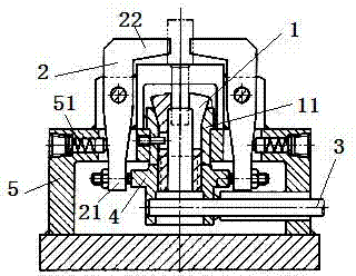
[0009] Such as figure 1 As shown, the cam clamping device of the present invention includes a clamping device, a force applying device and a reset device. The clamping device includes an elastic collet 1 for clamping the workpiece from the inside and a jaw 2 for clamping the workpiece from the outside. The outside of the jacket 1 is provided with an extrusion sleeve 11; the force application device includes a force application handle 3, which is fixedly connected to the cam 4, the inner side of the cam 4 is threaded to the elastic collet 1, the outer side of the cam 4 and the driving end of the jaw 2 21 contacts, the jaws 2 are fixed on the support 5 through the hinge point, the driven end 22 of the jaws 2 is a chuck for clamping the workpiece, and the support 5 is provided with a return spring 51 of the jaws.

[0010] By turning the force-applying handle 3 and turning the cam 4, the elastic collet 1 is driven to move down because the inner side of the cam 4 is threaded to con...


PUM


Abstract

The invention discloses a cam clamping device which comprises a clamping device, a force applying device and a reset device. The clamping device comprises an elastic clamping sleeve and a clamping jaw, wherein the elastic clamping sleeve clamps workpieces from the inner portion, and the clamping jaw clamps the workpieces from the outer portion. An extruding sleeve is arranged at the outer portion of the elastic clamping sleeve. The force applying device comprises a force applying handle which is fixedly connected with a cam. The elastic clamping sleeve is connected with the inner side of the cam in a threaded mode. The outer side of the cam contacts with a drive end of the clamping jaw. The clamping jaw is fixed on a support through a hinge joint point. A driven end of the clamping jaw is a clamping head of a clamping workpiece. A reset spring of the clamping jaw is arranged on the support. The force applying handle is rotated to enable the ram to rotate. The elastic clamping sleeve is connected with the inner side of the cam in the threaded mode to drive the elastic clamping sleeve to move down. Due to the fact that the extruding sleeve is arranged at the outer portion of the elastic clamping sleeve, the elastic clamping sleeve clamps the workpieces from the inner portion. Meanwhile, the outer side of the cam contacts with the drive end of the clamping jaw to drive the clamping jaw to clamp the workpieces from the outer portion, and thereby the workpieces are achieved to be clamped from the inner portion and the outer portion through the cam.

Description

technical field [0001] The invention relates to a clamp for processing, in particular to a cam clamping device. Background technique [0002] Fixtures are used in the process of mechanical manufacturing to fix the processing object so that it occupies the correct position to accept construction or testing devices. In a broad sense, any process in the process, the device used to install the workpiece quickly, conveniently and safely, can be called a fixture. Such as welding fixtures, inspection fixtures, assembly fixtures, machine tool fixtures, etc. Among them, machine tool fixtures are the most common, often referred to as fixtures. When machining a workpiece on a machine tool, in order to make the surface of the workpiece meet the technical requirements such as the size, geometric shape, and position accuracy with other surfaces specified in the drawing, the workpiece must be positioned and clamped before processing. Some workpieces need to be clamped from the inside an...

Claims


Application Information

Patent Timeline
Patent Type & Authority Applications(China)
IPC IPC(8): B23Q3/00
Inventor 姜静慧
Owner CHONGQING MING SHIELD ELECTROMAGNETIC VALVE
Why Eureka
Try Eureka