Rotary type vacuum adsorption die

A vacuum adsorption and rotary technology, applied in the direction of manufacturing tools, clamping, supporting, etc., can solve the problems that are unfavorable for the survival and development of furniture manufacturers, the requirements for the operator's technical level are also high, and cannot meet the processing needs, etc., to achieve Solve the problem of positioning and clamping, the structure is simple and reasonable, and the effect of low cost

Pending Publication Date: 2018-12-21
HEBEI BLUEBIRD FURNITURE CO LTD
View PDF11 Cites 3 Cited by
  • Summary
  • Abstract
  • Description
  • Claims
  • Application Information

AI Technical Summary

Problems solved by technology

[0002] At present, the production of furniture is diversified. In order to meet the market demand, the processing requirements for furniture parts have also been improved. The general three-axis machining center is often unable to meet the processing requirements when it needs to process four-dimensional space and five-dimensional space for furniture parts. Especially for the clamping and positioning requirements of furniture components
[0003] In order to overcome the above technical problems, most manufacturers meet the multi-dimensional production needs of furniture parts by purchasing four-dimensional machining centers and five-dimensional machining centers. Five-dimensional space processing needs, but for small furniture manufacturers, four-dimensional machining centers and five-dimensional machining centers not only have high equipment costs, but also complicated programming, and require high technical level of operators, which is not conducive to furniture manufacturers. survival and development

Method used


Image

  • Rotary type vacuum adsorption die
  • Rotary type vacuum adsorption die
  • Rotary type vacuum adsorption die

Examples


Embodiment 1

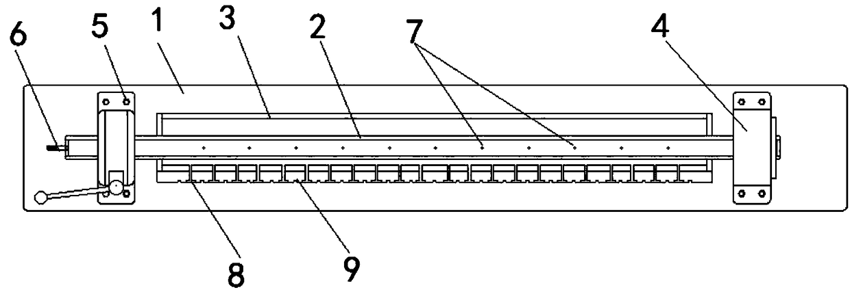
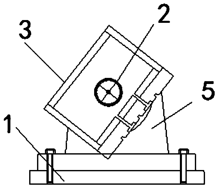
[0031] like Figure 1~4 As shown, the present embodiment provides a rotary vacuum adsorption mould, including a support base 1, a vacuum ventilation pipe 2 and an adsorption mold 3, the adsorption mold 3 is sleeved on the outer periphery of the vacuum ventilation pipe 2, and the two ends of the adsorption mold 3 are connected to the The outer walls of the vacuum vent pipe 2 are sealed, and the two ends of the support base 1 are respectively provided with a first bearing support 4 and a second bearing support 5, and the two ends of the vacuum vent pipe 2 are respectively installed on the first bearing support through bearings. 4 and the second bearing support 5, wherein the installation method of the bearing used to realize the vacuum vent pipe 2 is a conventional bearing method, and the bearing types that can realize the rotation of the vacuum vent pipe 2 can be adaptively applied to this embodiment , no longer go into details here; one end of the vacuum vent pipe 2 is closed,...


PUM


Abstract

The invention discloses a rotary type vacuum adsorption die. An adsorption die is arranged on the outer periphery of a vacuum vent pipe in a sleeving manner. The two ends of the vacuum vent pipe are installed on a first bearing support seat and a second bearing support seat through bearings correspondingly. One end of the vacuum vent pipe is closed, and the other end of the vacuum vent pipe is provided with a vacuumizing connector. The side wall of the vacuum vent pipe is provided with multiple vent holes. The outer surface of the adsorption die is provided with multiple adsorption through holes and multiple grooves to form an adsorption surface, and the adsorption surface is used for holding a to-be-machined furniture component. According to the machining demand of the furniture component, the rotary type vacuum adsorption die is fixed to a table top of a three-dimensional machining center, through the vacuumizing connector, the inner portion of the vacuum vent pipe is vacuumized, theto-be-machined furniture component is adsorbed to the adsorption surface, the vacuum vent pipe is rotated to adjust the rotation inclination angle of the to-be-machined furniture component, so that the four-dimension machining demand of the to-be-machined furniture component, the to-be-machined component, can be met, and therefore the locating and clamping problems existing when a three-dimensionmachining center machines a four-dimension space furniture component are solved.

Description

technical field [0001] The invention relates to the field of multidimensional processing, in particular to a rotary vacuum adsorption mold. Background technique [0002] At present, the production of furniture is diversified. In order to meet the market demand, the processing requirements for furniture parts have also been improved. The general three-axis machining center is often unable to meet the processing requirements when it needs to process four-dimensional space and five-dimensional space for furniture parts. Especially for the clamping requirements and positioning requirements of furniture components. [0003] In order to overcome the above technical problems, most manufacturers meet the multi-dimensional production needs of furniture parts by purchasing four-dimensional machining centers and five-dimensional machining centers. Five-dimensional space processing needs, but for small furniture manufacturers, four-dimensional machining centers and five-dimensional mac...

Claims


Application Information

Patent Timeline
Patent Type & Authority Applications(China)
IPC IPC(8): B23Q3/08
CPCB23Q3/088
Inventor 贾焱李建华宋孟华肖许华冯桂平刘志军谢丽霞文利兴贾新平
Owner HEBEI BLUEBIRD FURNITURE CO LTD
Why Eureka
Try Eureka