Steel reinforcement cage for filling pile and filling pile construction method using steel reinforcement cage

A technology of reinforced cages and cast-in-place piles, applied in sheet pile walls, foundation structure engineering, construction, etc., can solve problems such as loss of concrete mud, potential safety hazards, unqualified cast-in-place piles, etc., to ensure the quality of piles and eliminate potential safety hazards Effect

Active Publication Date: 2013-05-22
MCC COMM CONSTR GRP CO LTD
View PDF4 Cites 7 Cited by
  • Summary
  • Abstract
  • Description
  • Claims
  • Application Information

AI Technical Summary

Problems solved by technology

[0005] The disadvantage of the above steel cage 100' and the cast-in-situ pile construction method using it is that if there is a water layer in the formation where the pile is formed, then during the pile formation process, flowing groundwater will enter the pile hole and wash the pile. The concrete that has not yet initially set or has already set in the hole will cause the mud in the concrete to lose, and even cause segregation, voids, or even pile breakage in the pile foundation concrete, which will lead to unqualified quality of cast-in-place piles and bring hidden dangers to safety

Method used


Image

  • Steel reinforcement cage for filling pile and filling pile construction method using steel reinforcement cage
  • Steel reinforcement cage for filling pile and filling pile construction method using steel reinforcement cage
  • Steel reinforcement cage for filling pile and filling pile construction method using steel reinforcement cage

Examples


Embodiment Construction

[0023] Embodiments of the reinforcement cage for cast-in-place pile and the construction method of cast-in-situ pile using the same according to the present invention will be described below with reference to the accompanying drawings. As those skilled in the art would realize, the described embodiments may be modified in various different ways, all without departing from the spirit and scope of the present invention. Accordingly, the drawings and description are illustrative in nature and not intended to limit the scope of the claims. In addition, in this specification, the same reference numerals denote the same or similar parts.

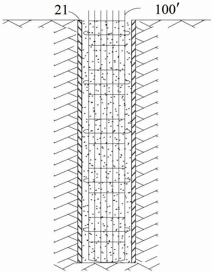
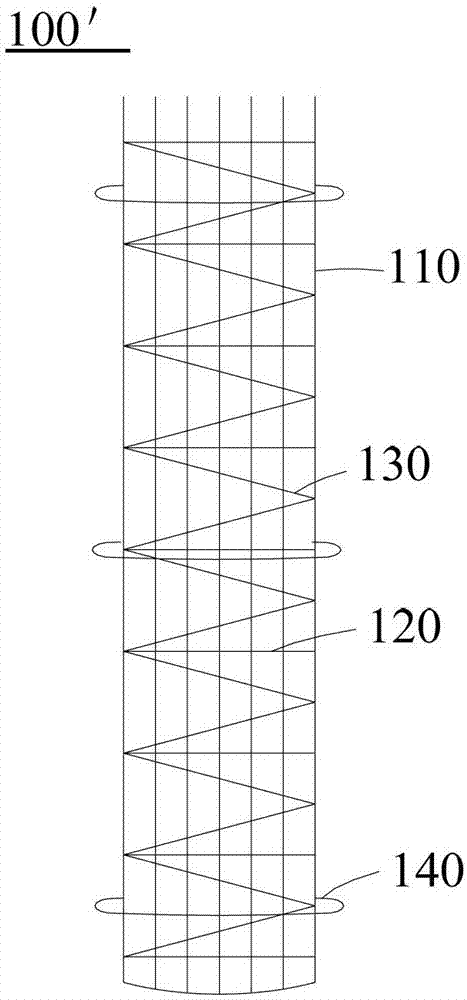
[0024] image 3 The schematic diagram shows the structure of the reinforcement cage for cast-in-situ piles described in one embodiment of the present invention. Figure 4a and Figure 4b The detailed structure of the anti-scour hoop and the grouting pipe on the reinforcement cage described in this embodiment is shown. Such as image 3 As show...


PUM


Abstract

The invention provides a steel reinforcement cage for a filling pile and a filling pile construction method using a steel reinforcement cage. The steel reinforcement cage for the filling pile comprises a cage body, at least one anti-scour protective hoop and a plurality of grounting pipes. Each anti-scour protective hoop is arranged on a pre-arranged position outside the cage body, encircles the cage body, and comprises a steel reinforcement framework encircling and fixed on a pre-arranged position outside the cage body, a fine mesh wire net fixed on the steel reinforcement framework, and a slurry layer coated on the fine mesh wire net fine mesh wire net. The plurality of grounting pipes are fixed outside the cage body and extend along the lengthwise direction of the cage body, and slurry outlets of the grounting pipes expose outside each anti-sour protective hoop. In the construction process of the filling pile by using the steel reinforcement cage, anti-sour protective hoops on the steel reinforcement protective hoop ensure that water on an underwater layer can not directly generate scour on concrete in the filling pile. Furthermore, the grounting pipes on the steel reinforcement cage fill slurry between the anti-scour protective hoops and a pile hole wall, and accordingly water seams are plugged by the slurry, and the pile hole wall is strengthened.

Description

technical field [0001] The invention relates to the construction field, in particular to a reinforcement cage for cast-in-place piles and a construction method for cast-in-situ piles using the reinforcement cage. Background technique [0002] Cast-in-situ piles are the basic structures commonly used in buildings, roads, bridges, docks and other buildings, and are usually formed by impacting holes and pouring piles. At present, a large class of cast-in-situ piles adopts the method of mud retaining wall to protect the pile hole and prevent the hole wall from collapsing in the process of forming the pile hole. [0003] Figure 1a and 1b It is a schematic diagram showing an existing cast-in-place pile construction method. First, if Figure 1a As shown, the steel casing 10 is buried, and then the inside of the steel casing 10 is excavated downward by means of drilling rigs and high-pressure water jets to form pile holes 20, wherein the steel casing 10 can prevent the hole from ...

Claims


Application Information

Patent Timeline
Patent Type & Authority Applications(China)
IPC IPC(8): E02D5/34E02D5/38E02D15/04
Inventor 刘思谋
Owner MCC COMM CONSTR GRP CO LTD
Why Eureka
Try Eureka