
Pile end grouting spray head

A grouting head and grouting technology, used in construction, infrastructure engineering and other directions, can solve problems such as endangering the safety and durability of building structures, failing to ensure the smooth shedding of tapes or plastic films, and failing to meet design requirements for foundation bearing capacity. , to ensure the success rate of grouting and the quality of piles, improve the efficiency of construction operations, and improve the quality of piles

Pending Publication Date: 2019-11-26
MCC CAPITAL ENGINEERING & RESEARCH
View PDF0 Cites 7 Cited by
  • Summary
  • Abstract
  • Description
  • Claims
  • Application Information

AI Technical Summary

Problems solved by technology

The nozzle structure at the end of the grouting pipe is the key to whether the grouting can be carried out smoothly. However, the grouting pipes and nozzles used in the post-grouting process are mostly made on site. Take small-diameter holes, set the holes at a certain distance, and spirally stagger along the pipe circumference, wrap the outside with two layers of tape, plastic film or rubber film, etc., and wrap them tightly with iron wires. In the actual construction process on site, there is no guarantee The tape or plastic film wrapped on the outside falls off smoothly, and it is difficult to ensure the smoothness of the grouting hole, resulting in the failure of the grouting operation to be completed smoothly, the success rate of the grouting is low, the quality of the pile body is difficult to guarantee, and the bearing capacity of the foundation cannot meet the design requirements, thus endangering the building structure The use of safety and durability

Method used


Image

  • Pile end grouting spray head
  • Pile end grouting spray head
  • Pile end grouting spray head

Examples


Embodiment Construction

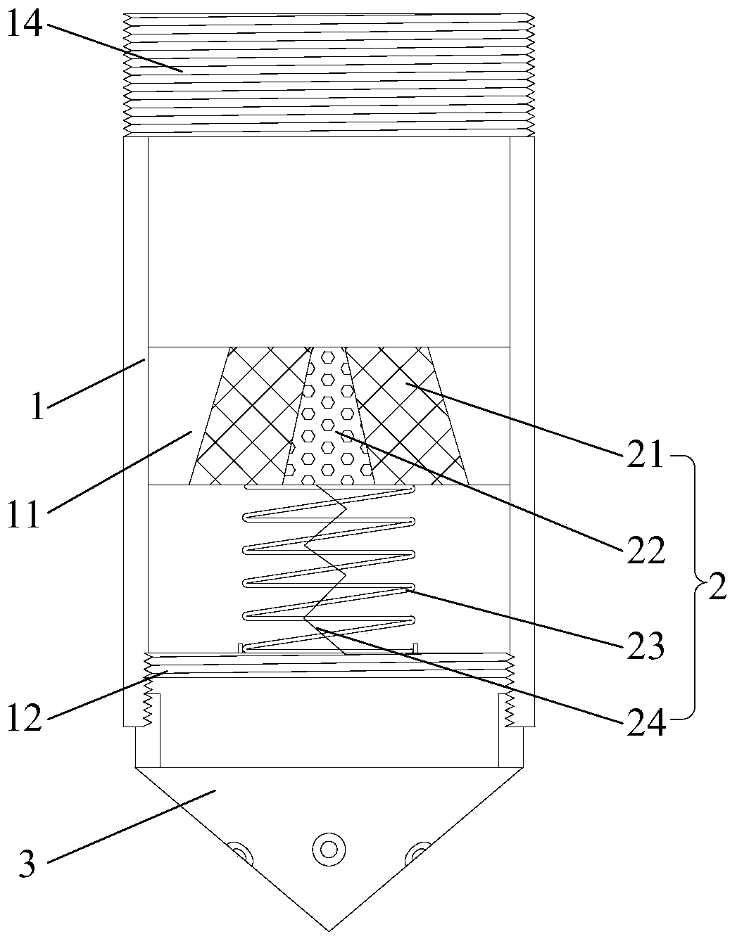
[0042] In order to have a clearer understanding of the technical solutions, objectives and effects of the present invention, the specific implementation manners of the present invention will now be described with reference to the accompanying drawings. Wherein, the use of adjective or adverbial modifiers "upper" and "lower", "inner" and "outer" is only to facilitate relative reference between groups of terms, and does not describe any specific relationship to the modified term. Orientation constraints. In addition, the terms "first", "second" and so on are only used for descriptive purposes, and cannot be understood as indicating or implying relative importance or implicitly specifying the number of indicated technical features. Therefore, the definition of "first" , "second", etc. may expressly or implicitly include one or more of these features. In the description of the present invention, unless otherwise specified, "plurality" means two or more.

[0043] Such as figure ...


PUM


Abstract

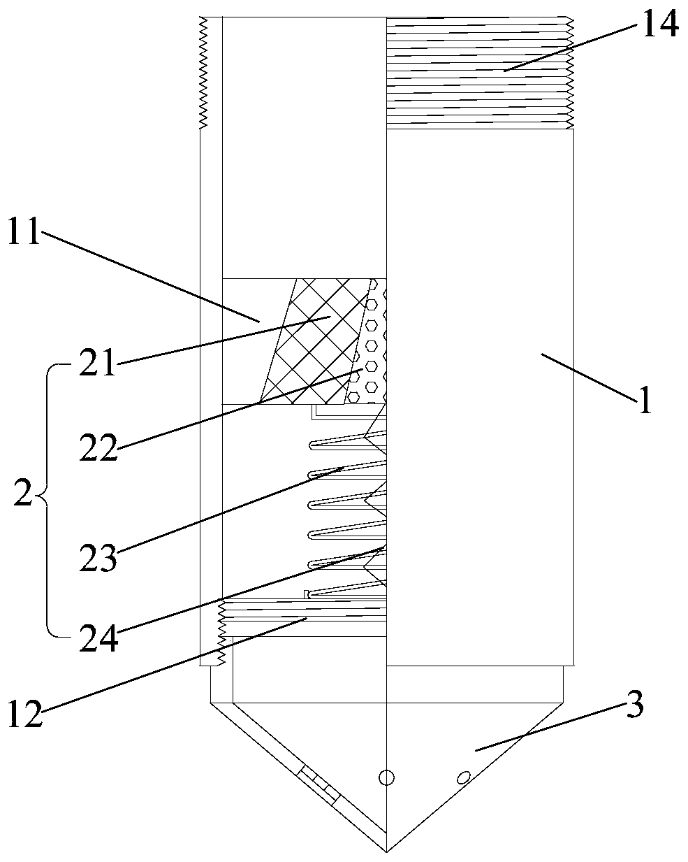
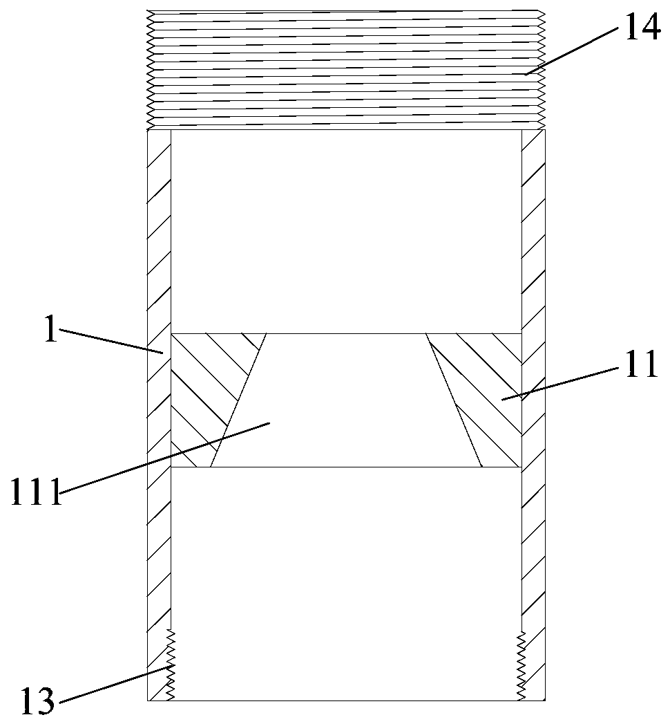
The invention provides a pile end grouting spray head. The pile end grouting spray head comprises a grouting pipe, an adjusting assembly and a grouting head, wherein a baffle and a base are connectedin the grouting pipe in the grouting direction in a spaced mode; the baffle is provided with a first grout outlet hole, and the base is provided with grout passing holes; the adjusting assembly can bemovably arranged in the first grout outlet hole; the adjusting assembly comprises at least two pistons arranged in a sleeving mode from inside to outside in sequence; the pistons are connected with the base through corresponding elastic parts, and the elastic force of the elastic parts connected with the corresponding pistons increases progressively in sequence from inside to outside; the grouting head is connected to the grout outlet end of the grouting pipe and is provided with grouting holes. Through the pile end grouting spray head provided by the invention, under the condition that grouting pressure meets the using requirement, the first grout outlet hole can be opened smoothly to complete grouting operation. The pile end grouting spray head can adjusting the grout flow according tothe grouting pressure to ensure that the grout flow meets the using requirement.

Description

technical field [0001] The invention relates to the technical field of construction engineering, in particular to a pile end grouting nozzle. Background technique [0002] In order to ensure the bearing capacity of the pile foundation, post-grouting is a process in the construction of the pile foundation. Generally, after the concrete pouring of the pile foundation is completed and the strength meets the requirements, the pile bottom and the pile body will be repaired through the grouting pipe buried in advance. Pile side grouting is used to improve the bearing capacity of the foundation and ensure the quality of foundation construction. During the post-grouting, the cement slurry is pressed into the pile tip through the grouting pipe, and first combined with the sediment at the pile tip, the segregated "virtual tip" and "dry ballast" to enhance the compactness of this part and improve the bearing capacity of the soil The grout goes back up along the joint layer of the pile...

Claims


Application Information

Patent Timeline
Patent Type & Authority Applications(China)
IPC IPC(8): E02D15/02E02D15/04
CPCE02D15/02E02D15/04
Inventor 王雪宝于庆坤
Owner MCC CAPITAL ENGINEERING & RESEARCH
Learn More