Current limiting device with hole diameter adjustable

A current-limiting device and adjustable technology, which is applied in the direction of production fluid, wellbore/well components, earthwork drilling and production, etc., can solve the problems of ineffective use of heat energy, imprecise management of oil wells, and prolonging self-spraying time, etc., to achieve the purpose of prolonging oil well Self-spray cycle, long service life, and the effect of extending the self-spray cycle

Inactive Publication Date: 2013-05-22
KARAMAY SHENGLI PLATEAU MACHINERY CO LTD
View PDF6 Cites 6 Cited by
  • Summary
  • Abstract
  • Description
  • Claims
  • Application Information

AI Technical Summary

Problems solved by technology

[0004] 1. Inaccurate, difficult to control, serious loss of heat energy;
[0005] Second, the thermal energy cannot be effectively used to prolong the self-spraying time, resulting in imprecise oil well management and untimely

Method used


Image

  • Current limiting device with hole diameter adjustable
  • Current limiting device with hole diameter adjustable
  • Current limiting device with hole diameter adjustable

Examples


Embodiment Construction

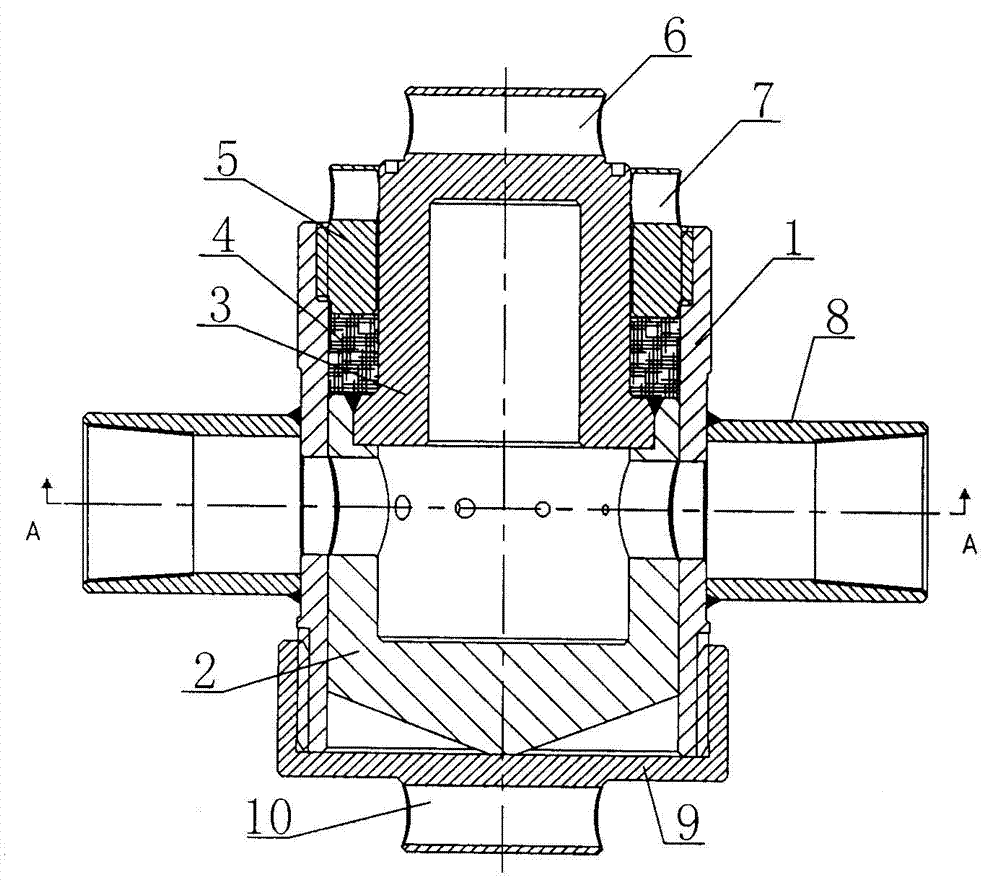
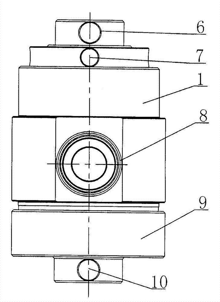
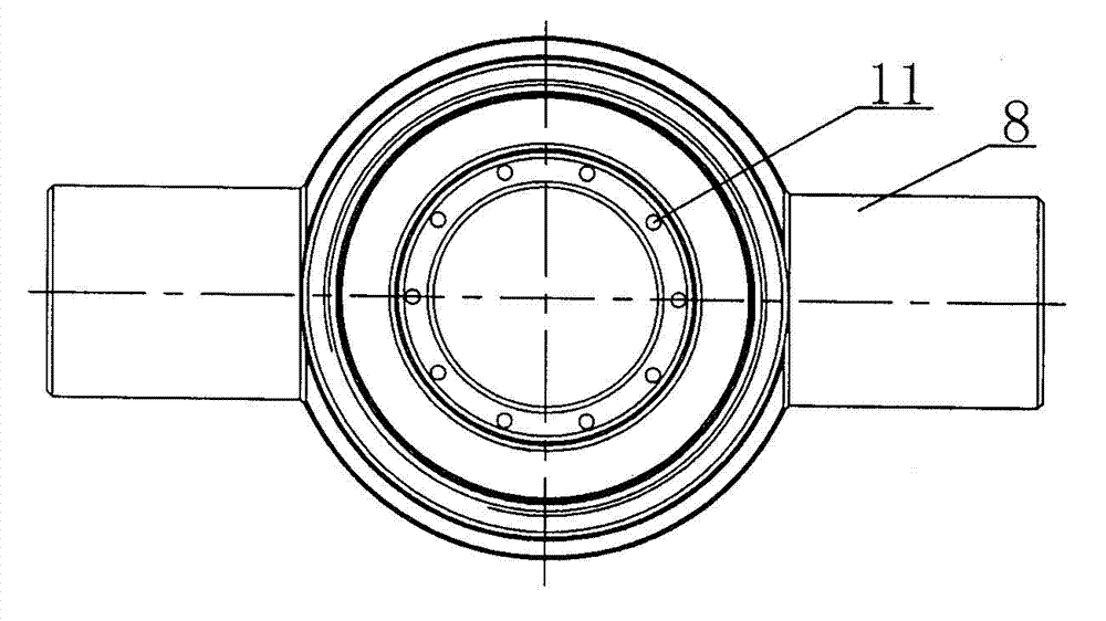
[0019] A flow-restricting device with adjustable pore size, such as figure 1 , figure 2 , image 3 , Figure 4 As shown, the rotatable mandrel is fitly installed in the cylindrical mandrel seat 1, and two symmetrical through holes are arranged on the wall of the mandrel seat 1. The outer connecting pipe 8 of the internal thread, the cap 9 is installed through the thread on one end of the mandrel seat 1; the stepped rotatable mandrel is composed of the mandrel 2 and the reduced-diameter connecting shaft 3, and has a cylindrical closed cavity core The shaft 2 is in dynamic fit with the inner hole of the mandrel seat 1. On the mandrel 2, through holes arranged symmetrically from small to large are evenly arranged in the radial direction. Among them, the two symmetrical through holes with the largest diameters on the mandrel 2 The diameters of the two symmetrical through holes on the mandrel base 1 are equal, and the coaxial lines are matched, and the inner hole of the compres...


PUM


Abstract

The invention discloses a current limiting device with a hole diameter adjustable. Two symmetric through holes are formed in a cylinder wall of a mandrel seat. The portions, with the two through holes, of the cylinder wall are respectively and fixedly connected with an outer connecting tube with inner threads. A cylinder opening at one end of the mandrel seat is provided with a sealing cover through threads. A mandrel in a stepped shape and capable of rotating is composed of the mandrel and a hole shrinkage connecting shaft. The mandrel with a cylindrical sealing cavity is matched with an inner hole of the mandrel seat in a movable mode. Through holes arranged symmetrically and with hole diameters enlarged gradually are formed in the mandrel along the radial direction. The two symmetric through holes in the mandrel with the largest diameters and the two symmetric through holes in the mandrel seat are the same in the hole diameter and are matched in a mode of coaxial line. A cylinder opening of the other end of the mandrel seat is provided with a gland nut through threads. An inner hole of the gland nut is movably matched with the connecting shaft. The connecting shaft between a mandrel bumper and the gland nut is provided with a sealing piece. According to the current limiting device with the hole diameter adjustable, under the condition that shutdown operation is not needed, the hole diameter of an oil nozzle can be adjusted conveniently to adjust flow and oil extraction differential pressure can be adjusted and controlled according to variation of oil temperature so that blowing period of an oil well can be prolonged, operation is simple and time and labor are saved.

Description

technical field [0001] The invention relates to the technical field of petroleum exploitation, and belongs to flow control equipment for wellhead production fluid, in particular to a flow limiting device with adjustable pore diameter. Background technique [0002] At present, in the process of oil production, in order to control the production pressure difference of the oil production wellhead and achieve the purpose of throttling and venting for production, fixed nozzle sleeves are often used. The outer thread of the oil nozzle is connected with the inner thread of the nozzle sleeve, and different flow limiting requirements can be achieved by replacing the oil nozzle with different specifications and apertures. When it is necessary to change the diameter of the fixed oil nozzle for steam injection or pumping, the oil nozzle cover end cover can only be removed after the well is shut down and the pressure is relieved to replace the fixed oil nozzle. [0003] To sum up, the ...

Claims


Application Information

Patent Timeline
Patent Type & Authority Applications(China)
IPC IPC(8): E21B43/12
Inventor 荣雁夏立元杨国华白连生王良明吕向升吕俊锋
Owner KARAMAY SHENGLI PLATEAU MACHINERY CO LTD
Why Eureka
Try Eureka