
A device and method for testing the running time of a gas lift production plunger

A technology of running time and testing device, applied in construction and other directions, can solve the problem of not being able to record the running time of the plunger and analyzing the force condition of the plunger.

Active Publication Date: 2021-01-29
PETROCHINA CO LTD
View PDF6 Cites 0 Cited by
  • Summary
  • Abstract
  • Description
  • Claims
  • Application Information

AI Technical Summary

Problems solved by technology

[0005] The device provided by the prior art can measure the temperature, pressure and liquid flow rate of the plunger gas lift, and cannot analyze the force condition of the plunger by recording the running time of the plunger through the test

Method used


Image

  • A device and method for testing the running time of a gas lift production plunger
  • A device and method for testing the running time of a gas lift production plunger
  • A device and method for testing the running time of a gas lift production plunger

Examples


Embodiment Construction

[0087] Unless otherwise defined, all technical terms used in the embodiments of the present invention have the same meanings as commonly understood by those skilled in the art. In order to make the object, technical solution and advantages of the present invention clearer, the implementation manner of the present invention will be further described in detail below in conjunction with the accompanying drawings.

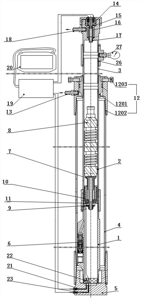
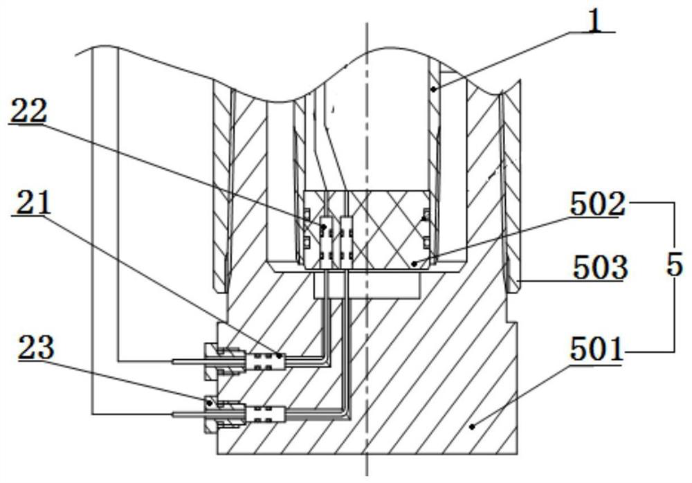
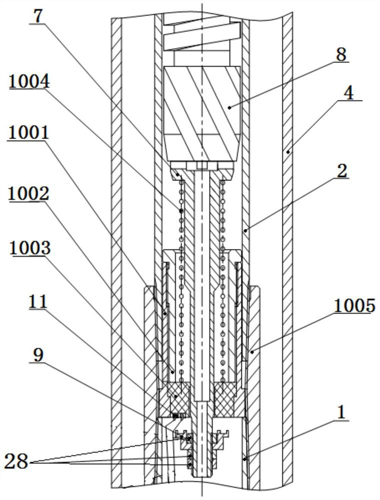
[0088] The invention provides a gas lift production plunger running time testing device, as attached figure 1 As shown, the device includes a gas lift valve mandrel 1, an inner pipe nipple 2, an inner pipe 3 connected in sequence from bottom to top, and an annular space that is sleeved outside the gas lift valve mandrel 1 and the inner pipe nipple 2. The outer tube 4, the lower blocking part 5, the gas lift valve 6, the plunger holder 7, the lower connecting ring 9, the first elastic fixing part 10, the first conductive ring 11, the middle blocking part 12, the upper b...


PUM


Abstract

The invention discloses a device and a method for testing the running time of a gas-lift oil production plunger, belonging to the field of oilfield testing. The device includes a gas lift valve work cylinder, an inner pipe nipple, an inner pipe, and an outer pipe connected in sequence, and is used to block the lower end of the outer pipe and the lower end of the gas lift valve work cylinder; the air outlet of the gas lift valve is connected with the gas The inner cavity of the working cylinder for lifting the valve is connected; the upper end of the plunger holder is used to place the plunger, and the lower end is provided with an electric ring connected to the lower end, so as to act as the first elasticity in the inner cavity of the connection between the working cylinder of the gas lift valve and the short joint of the inner pipe. The two first conductive rings at the lower end of the fixing part are connected; the middle blocking part to block the upper end of the outer pipe is provided with an air inlet joint; The two second conductive rings connected by the sliding upper electric tube; when the first conductive ring and the lower electric ring are connected or the second conductive ring is connected with the upper electric tube, the timing electric control box receives the start or stop Timing signal, and send timing start or stop timing control instructions to the electronic stopwatch.

Description

technical field [0001] The invention relates to the field of oilfield testing, in particular to a device and method for testing the running time of a gas-lift oil production plunger. Background technique [0002] With the reduction of crude oil self-spraying production in the oil well, or after the oil well loses the self-spraying ability, the production of crude oil can be increased by means of plunger gas lift to maintain the self-spraying production of the oil well. Among them, the plunger can move up and down in the wellhead Christmas tree and the tubing. When the fluid pressure and flow in the tubing string are not enough to lift the plunger, the plunger moves downward under the action of its own gravity. The fluid (gas and liquid mixture) flows into the upper end of the plunger through the gap between the outer edge of the plunger and the inner wall of the tubing; when the fluid pressure at the lower end of the plunger rises, the plunger is lifted to the wellhead, and ...

Claims


Application Information

Patent Timeline
Patent Type & Authority Patents(China)
IPC IPC(8): E21B47/008
CPCE21B47/008
Inventor 张昊王磊孙成林杨辉高文明高翔刘宇飞刘晓旭强晓光
Owner PETROCHINA CO LTD
Learn More